Adjusting Copy Image Area
D127/D128 4-62 SM
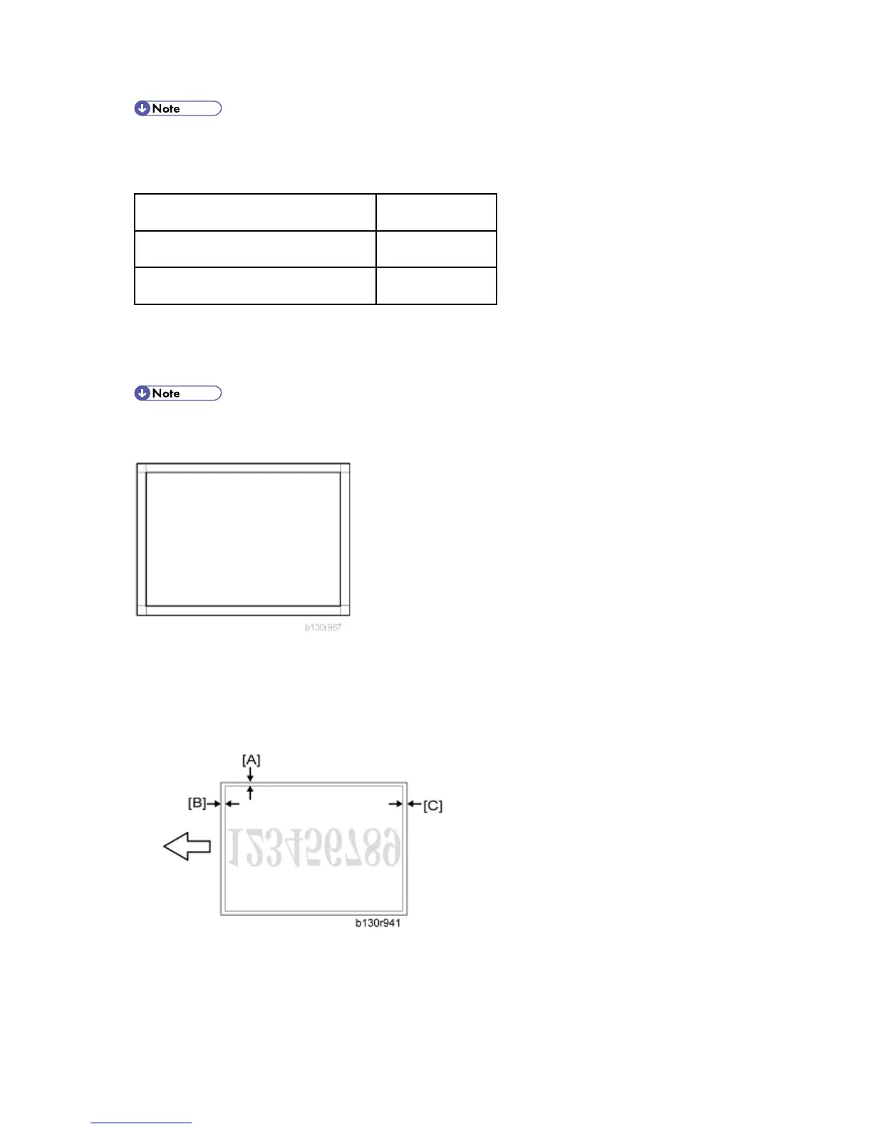
The diagrams show the paper on the copy tray. Note that the paper is output with the face
down.
SP Specification
SP2-102-001 (Main scan Mag.)
0 ± 0.5%
SP4-008-001 (Sub Scan Mag.)
0 ± 1.0%
4.14.3 DF IMAGE ADJUSTMENT
Perform the adjustment procedure in this section only when the ARDF is installed on the
copier.
1. Make a temporary test chart as shown in the above diagram. Use the "A4/8.5 x 11" paper to
make it.
2. Place the temporary test chart on the ARDF.
3. Make a copy.
4. Measure the distance between the side edge of the image area and the side edge of the
paper [A].
(The diagram shows the paper on the copy tray. Note that the paper is output with the face
down.)
 Loading...