3. WIRING
IMR02C15-E4
3-7
RB900
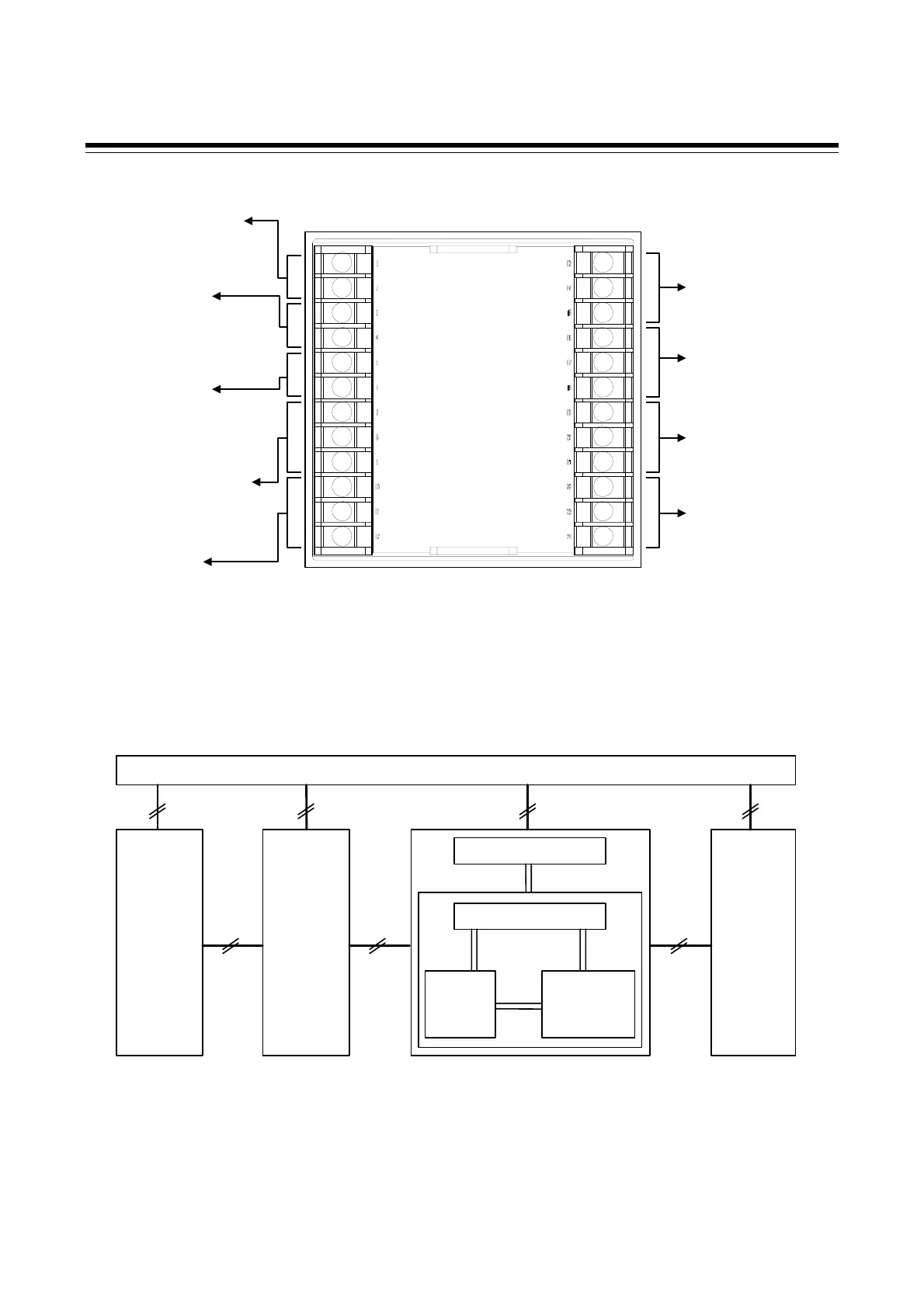
Isolations of input and output
For isolated device input/output blocks, refer to the following:
Power supply
Isolated IsolatedIsolated
Commu-
nication
(RS-485)
Digital
input
DI1
DI2
Digital
output
2
DO1
DO2
DO3
DO4
Output1
(OUT1)
Output2
(OUT2)
Non-isolated
Non-isolated
Isolated
Isolated
Isolated Isolated
MCU
Measured input
Loader
commu-
nication
CT input
(CT1, CT2)
1
Outputs are isolated if output 1 (OUT1) or output 2 (OUT2) is “relay contact output” or “triac trigger output.”
If both outputs are “relay contact output” or “triac trigger output,” outputs are not isolated.
2
Outputs of DO1/DO2 and DO3/DO4 are isolated.
DO1 and DO2 or DO3 and DO4 use the same common terminal (No. 9 for DO1/DO2, and No. 21 for DO3/DO4)
and are not isolated.
Output 2 (OUT2)
[Refer to P. 3-9]
Relay contact (1)/Voltage pulse/
Voltage/Current/Triac/
Open collector
Communication *
[Refer to P. 3-14]
RS-485
Power supply voltage
[Refer to P. 3-8]
100 to 240 V AC, 24 V AC,
24 V DC
Digital output 4 (DO4),
Digital output 3 (DO3) *
[Refer to P. 3-11]
Relay contact (2)
Digital input 2 (DI2),
Digital input 1 (DI1) *
[Refer to P. 3-13]
Dry contact input
Current transformer (CT)
input 2 (CT2),
Current transformer (CT)
input 1 (CT1) *
[Refer to P. 3-13]
Output 1 (OUT1)
[Refer to P. 3-9]
Relay contact (1)/Voltage pulse/
Voltage/Current/Triac/
Open collector
* Optional
13
14
15
16
17
18
19
20
21
22
23
24
1
2
3
4
5
6
7
8
9
10
11
12
Digital output 2 (DO2),
Digital output 1 (DO1) *
[Refer to P. 3-11]
Relay contact (2)
Measured input
[Refer to P. 3-12]
Thermocouple/RTD/Voltage/Current

 Loading...


