3. WIRING
3-2 IMR02C15-E4
3.1 Wiring Cautions
• For thermocouple input, use the appropriate compensation wire.
• For RTD input, use low resistance lead wire with no difference in resistance between the three lead
wires.
• To avoid noise induction, keep input signal wire away from instrument power line, load lines and
power lines of other electric equipment.
• If there is electrical noise in the vicinity of the instrument that could affect operation, use a noise filter.
− Shorten the distance between the twisted power supply wire pitches to achieve the most effective
noise reduction.
− Always install the noise filter on a grounded panel. Minimize the wiring distance between the
noise filter output and the instrument power supply terminals to achieve the most effective noise
reduction.
− Do not connect fuses or switches to the noise filter output wiring as this will reduce the
effectiveness of the noise filter.
• Allow approximately 5 seconds for contact output when the instrument is turned on. Use a delay
relay when the output line is used for an external interlock circuit.
• Power supply wiring must be twisted and have a low voltage drop.
• This instrument is not furnished with a power supply switch or fuse. If a fuse or power supply switch
is required, install close to the instrument.
Recommended fuse rating: Rated voltage 250 V, Rated current 1 A
Fuse type: Time-lag fuse
• For the current input specification, a shunt resistor of 250 Ω±0.02 % (Temperature characteristics:
±10 ppm/°C, Specified voltage: 0.25 W or more) must be connected between the input terminals.
• For an instrument with 24 V power supply, supply power from a SELV circuit.
• A suitable power supply should be considered in end-use equipment. The power supply must be in
compliance with a limited-energy circuits (maximum available current of 8 A).
• Use the solderless terminal appropriate to the screw size.
Screw size: M3 × 7 (With 5.8 × 5.8 square washer)
Recommended tightening torque:
0.4 N・m (4 kgf・cm)
Applicable wire: Solid/twisted wire of 0.25 to 1.65 mm
2
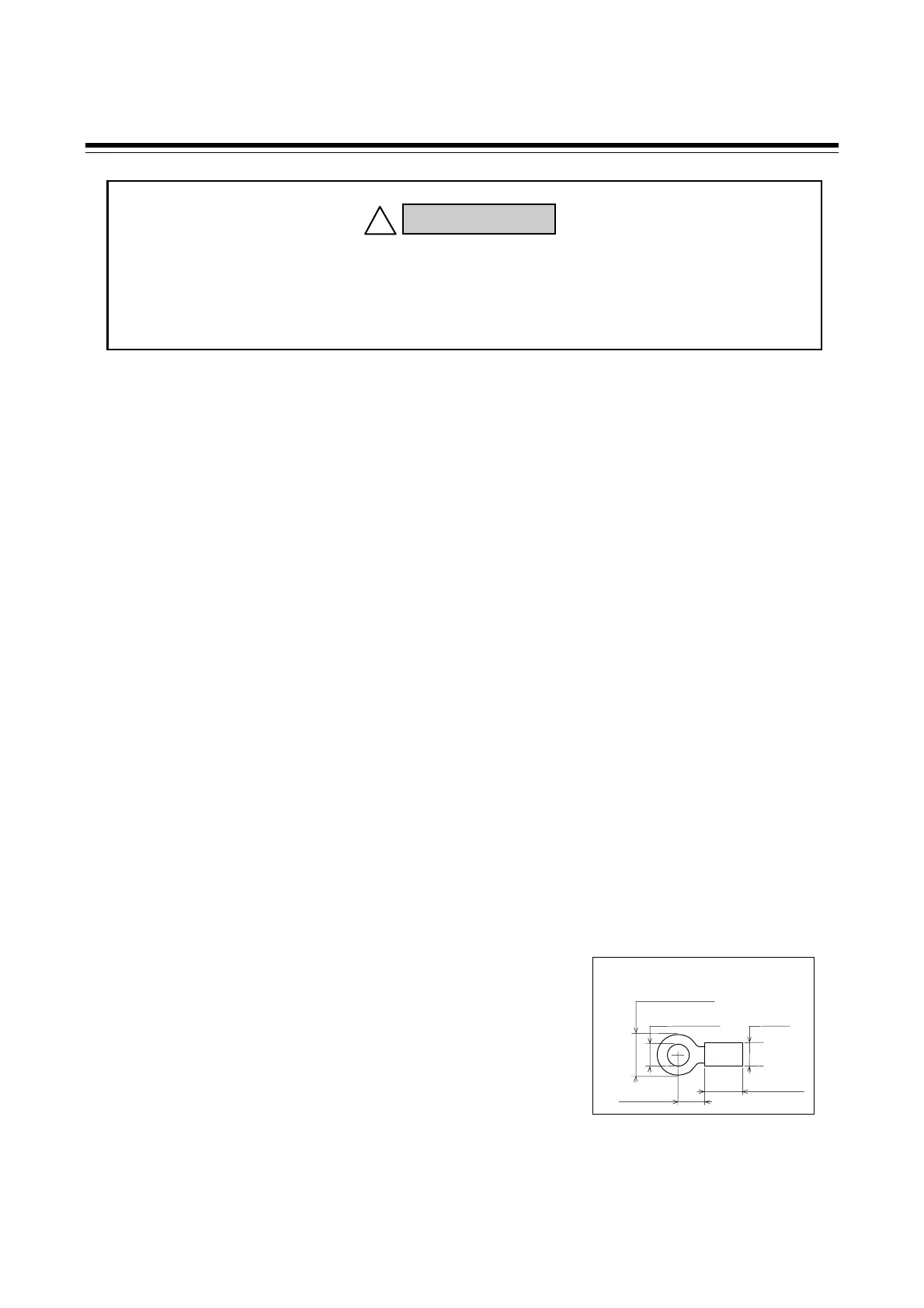
Specified dimension: Refer to Fig. 3.1
Specified solderless terminals:
Circular terminal with isolation V1.25-MS3
(M3 screw, width 5.5 mm, hole diameter 3.2 mm)
• Make sure that the any wiring such as solderless terminal is not in contact with the adjoining terminals.
Fig. 3.1
φ
3.2 MIN
φ
5.5 MAX
φ
5.0
5.6 mm
9.0 mm
To prevent electric shock or instrument failure, do not turn on the power until all
wiring is completed. Make sure that the wiring is correct before applying power
to the instrument.
WARNING
!

 Loading...


