3. WIRING
IMR02C15-E4 3-5
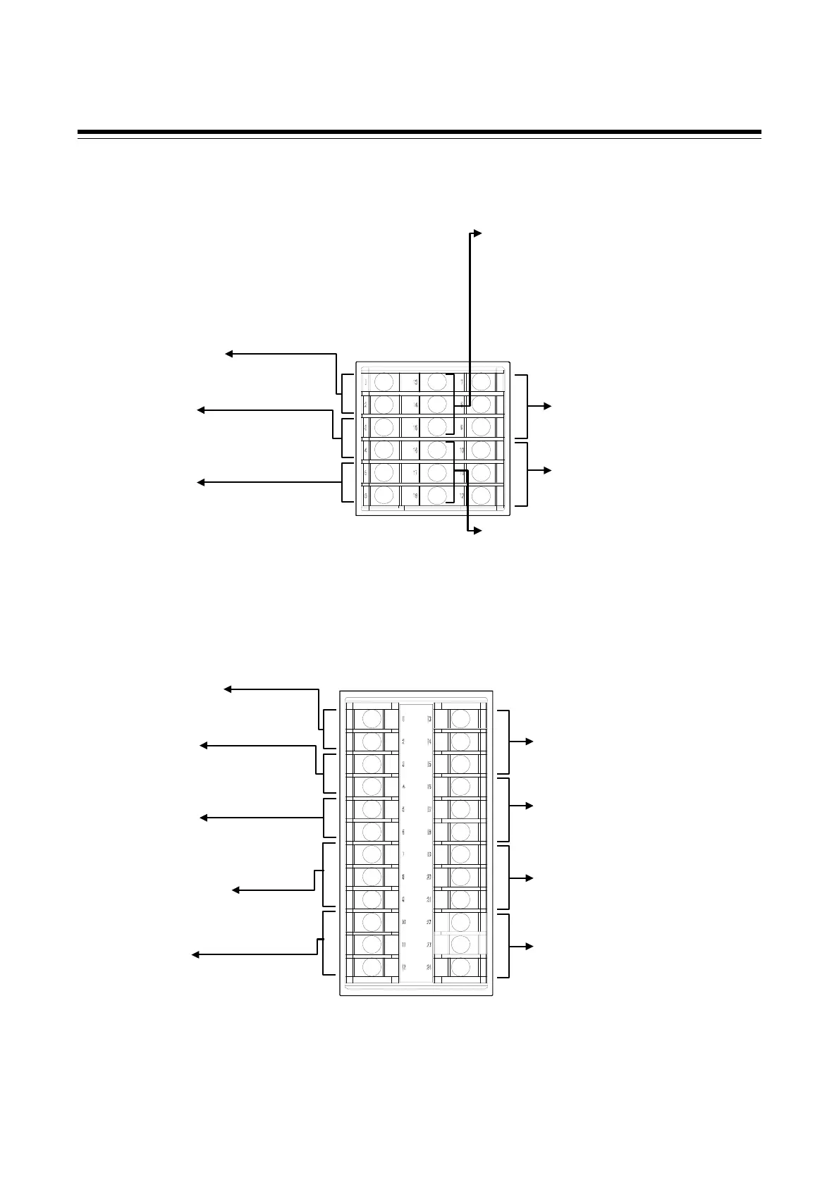
3.2 Terminal Layout
The terminal layout is as follows.
RB100
RB400
Output 2 (OUT2)
[Refer to P. 3-9]
Relay contact (1)/Voltage pulse/Voltage/Current/
Triac/Open collector
Power supply voltage
[Refer to P. 3-8]
100 to 240 V AC, 24 V AC, 24 V DC
Output 1 (OUT1)
[Refer to P. 3-9]
Relay contact (1)/Voltage pulse/Voltage/Current/
Triac/Open collector
Digital output 2 (DO2),
Digital output 1 (DO1) *
[Refer to P. 3-11]
Relay contact (2)
Measured input
[Refer to P. 3-13]
Thermocouple/RTD/Voltage/Current
Communication *
[Refer to P. 3-14]
RS-485
Digital output 4 (DO4),
Digital output 3 (DO3) *
[Refer to P. 3-11]
Relay contact (2)
Digital input 2 (DI2),
Digital input 1 (DI1) *
[Refer to P. 3-13]
Dry contact input
Current transformer (CT) input 2 (CT2),
Current transformer (CT) input 1 (CT1) *
[Refer to P. 3-13]
* Optional
13
14
15
16
17
18
19
20
21
22
23
24
1
2
3
4
5
6
7
8
9
10
11
12
713
6
5
4
3
2
1
11
10
9
8
12
17
16
15
14
18
Output 2 (OUT2)
[Refer to P. 3-9]
Relay contact (1)/Voltage pulse/Voltage/Current/
Triac/Open collector
Power supply voltage
[Refer to P. 3-8]
100 to 240 V AC, 24 V AC, 24 V DC
Output 1 (OUT1)
[Refer to P. 3-9]
Relay contact (1)/Voltage pulse/Voltage/Current/
Triac/Open collector
Digital output 2 (DO2),
Digital output 1 (DO1) *
[Refer to P. 3-11]
Rela
contact
2
Communication and Digital input (DI1, DI2)
• Communication *
[Refer to P. 3-14]
RS-485
• Digital input 2 (DI2)
Digital input 1 (DI1) *
[Refer to P. 3-13]
Dr
contact in
ut
Current transformer (CT) input 2 (CT2)
Current transformer (CT) input 1 (CT1) *
[Refer to P. 3-13]
* Optional
Measured input
[Refer to P. 3-12]
Thermocouple/RTD/Voltage/Current

 Loading...


