7. OPERATING ADDITIONAL FUNCTIONS
7-12 IMR02C15-E4
7.3 Transmission Output Function
The Transmission output function (optional) is outputting the state of Measured value (PV), Set value
(SV), or Manipulated output value (MV1) as a voltage or current signal. It is possible to record the
state of Measured value (PV) or Set value (SV) when connected to a recorder.
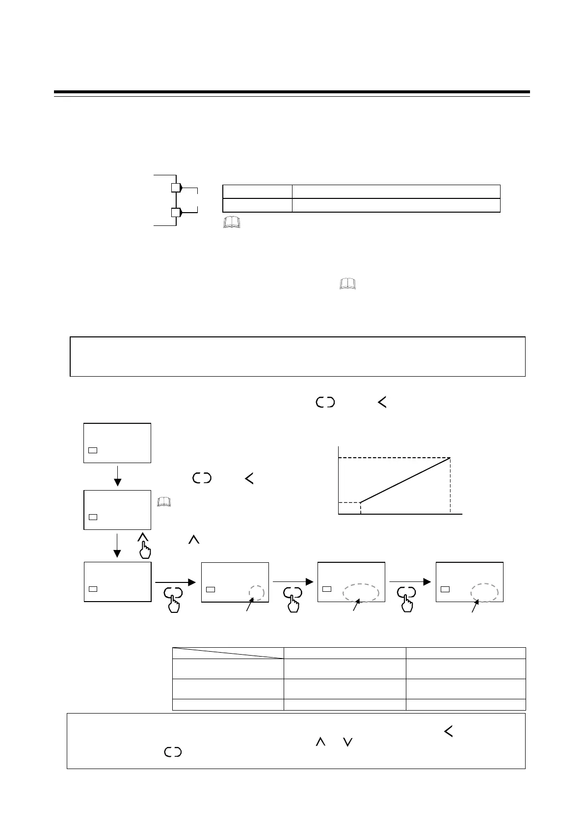
Terminal configuration
Setting procedure
If the Transmission output function will be used, set the following parameters in Engineering mode:
• Transmission output type • AO full scale adjustment value *
• Transmission output scale high • AO zero adjustment value *
• Transmission output scale low
* Do not change the factory set adjustment value for the AO full scale adjustment value and or the AO zero adjustment value as the
accuracy will be changed.
[Example: Scaling the Measured value (PV) to 50 to 250 °C before output (Output signal: 4 to 20 mA DC)]
In PV/SV monitor (the STOP state), press and hold the key and key for 4 seconds or more
to switch to Engineering mode and set each parameter in the F33.parameter group.
Transmission output scale high/low setting range:
Transmission output scale high Transmission output scale low
When Measured value (PV)
or Set value (SV) is selected
Transmission output scale low to
Input scale high
Input scale low to Transmission
output scale high
When Manipulated output
value (MV1) is selected
Transmission output scale low to
+105.0 %
−5.0 % to Transmission output
scale high
Factory set value High-limit value of input span Low-limit value of input span
Output signal type (Specify when ordering)
Voltage output
0 to 5 V DC, 0 to 10 V DC, 1 to 5 V DC
Current output
0 to 20 mA DC, 4 to 20 mA DC
Transmission output type:
0: Manipulated output
value (MV1)
1: Measured value (PV)
2: Set value (SV)
[Factory set value:
1: Measured value (PV)]
SET
R/S
The Transmission output function can only be used if the control action
is specified as PID action (direct or reverse) when the order is placed.
The Transmission output function parameters are set to “not displayed” in the factory default setting. Before
configuring the parameters, display the parameters by setting the Mode selection (no display) [ModE] parameter to
“128” in Function block 00 (F00) of Engineering mode. For the setting procedure, refer to 5.1 Initial Setting (P. 5-3).
Set value change and registration
• The blinking digit indicates which digit can be set. The blinking digit can be moved by pressing the key.
•
However, the changed data is not stored by the operation of the and keys alone. In order for the new parameter
value to be stored, the key must be pressed within 1 minute after the new value is displayed. The new value will
then be saved and the display will move to the next parameter.
R/S
SET
Transmission output
Measured
value (PV)
(Scaling value)
250 °C
50 °C
20 m
4 mA
28
STOP
SV1
F00.
SV1
F33.
SV1
AO
0001
SV1
F33.is a parameter
group related to input.
Press the key to
F33.
SET
AHS
0250
SV1
ALS
0050
SV1
Set the Transmission
output type to “1.”
Transmission output type
SET
SET
Set the Transmission output
scale high to “250.”
Set the Transmission output
scale low to “50.”
Transmission output scale high
Transmission output scale low
PV/SV monitor
(STOP state)
To display
F21.and following, make
sure that the
ModE parameter of
F00.is set to “128.”
Go to Engineering mode by pressing and
holding the key and keys for
4 seconds or more.
SET
R/S
Transmission output
(OUT2)
3
4
OUT2
+
−
Settings are configured in the STOP (control
STOP) state.

 Loading...


