6. OPERATIONS OF THE BASIC FUNCTIONS
IMR02C15-E4
6-30
Locking F21 to F91 data
To lock F21 to F91, set any value from “1” to “10” in the Set lock level, and enable the Data lock
function in the Set data unlock/lock screen.
When locked, the screens of F21 to F91 will not be displayed even if “128” is set in the Mode
selection (no display) screen of F00 in either RUN or STOP mode.
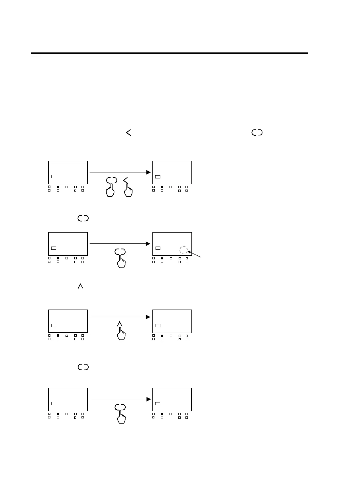
1. In PV/SV monitor, press the key for 4 seconds or more while pressing the key.
The display goes to the Engineering mode.
2. Press the key until Set lock level screen is displayed.
3. Press the key and set a value from “1” to “10.”
(Here “1” is set as an example.)
Set value and description
0: All parameter can be changed
1: Lock “Parameter Group” F01 through F10
2: Lock “Parameter Group” F02 through F10
3: Lock “Parameter Group” F03 through F10
4: Lock “Parameter Group” F04 through F10
5: Lock “Parameter Group” F05 through F10
6: Lock “Parameter Group” F06 through F10
7: Lock “Parameter Group” F07 through F10
8: Lock “Parameter Group” F08 through F10
9: Lock “Parameter Group” F09 and F10
10: Lock “Parameter Group” F10
4. Press the key to store the new value. The display goes to the next parameter.
SET
SET
R/S
F00.
SV1
OUT1
OUT
T
DO1 DO
MAN
STOP
DO3
DO4
LOcK
0000
SV1
OUT1
OUT
T
DO1 DO
MAN
STOP
DO3
DO4
Set lock level
Flashing
SET
LOcK
0000
SV1
OUT1
OUT
T
DO1 DO
MAN
STOP
DO3
DO4
LOcK
0001
SV1
OUT1
OUT
T
DO1 DO
MAN
STOP
DO3
DO4
Set lock level
SET
LOcK
0001
SV1
OUT1
OUT
T
DO1 DO
MAN
STOP
DO3
DO4
SET
MoNI
0000
SV1
OUT1
OUT
T
DO1 DO
MAN
STOP
DO3
DO4
Monitor selection
(no display)
28
200
SV1
OUT1
OUT
T
DO1 DO
MAN
STOP
DO3
DO4
PV/SV monitor
F00.
SV1
OUT1
OUT
T
DO1 DO
MAN
STOP
DO3
DO4
Engineering mode
Function block 00 (F00)
(4 seconds or more)
SET
R/S
+

 Loading...


