8. PARAMETER DESCRIPTION
IMR02C15-E4 8-43
8.5 Engineering Mode
The Engineering mode allows the control to be set according to application requirements.
For parameter details, refer to the 8.5.3 Engineering item list (P. 8-57).
To configure settings in Engineering mode (F21 to F70), the following steps must be
performed:
• Preset “0000” to the Set data unlock/lock transfer setting.
• Set STOP mode (control STOP) at the RUN/STOP transfer.*
* However, only checking can be made even in the RUN state.
To change the parameters in the Engineering mode from F21 to F70, preset “128” to the mode
selection at F00.
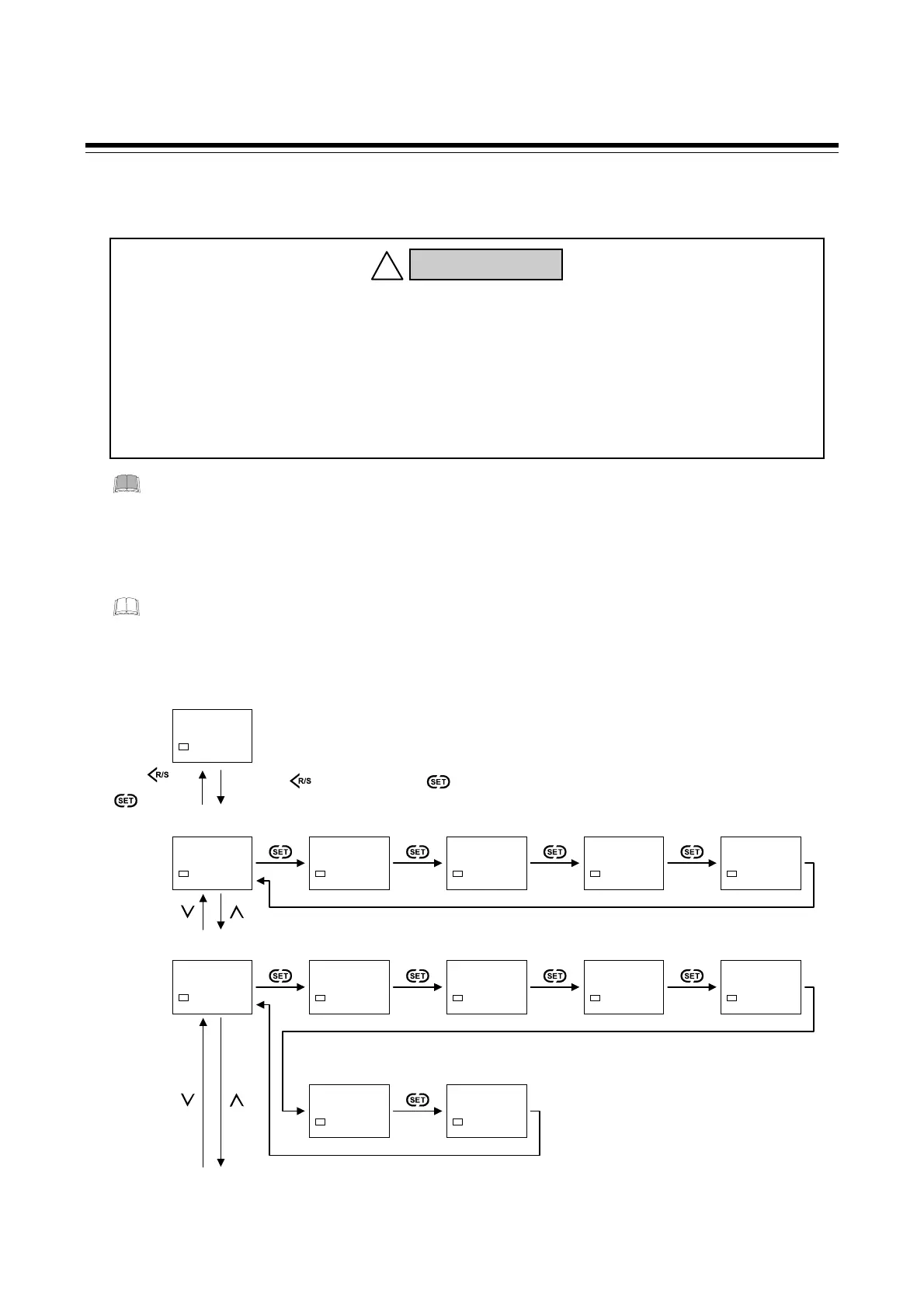
8.5.1 Display sequence
Continued on the next page.
Parameters in the Engineering mode (F21 to F70) should be set according to the
application before setting any parameter related to operation. Once the
parameters in the Engineering mode are set correctly, no further changes need
to be made to parameters for the same application under normal conditions.
If they are changed unnecessarily, it may result in malfunction or failure of the
instrument. RKC will not bear any responsibility for malfunction or failure as a
result of improper changes in the Engineering mode.
WARNING
!
PV/SV monitor
28$
200
SV1
(P. 8-7)
Function block 00
(F00)
F00.
SV1
(P. 8-57)
LOcK
0000
SV1
Set lock level
MONI
0000
SV1
Monitor selection
(no display)
MODE
0000
SV1
Mode selection
(no display)
R/S
0000
SV1
RUN/STOP
setting
(P. 8-57) (P. 8-58) (P. 8-58) (P. 8-59)
Function block 01
(F01)
F01.
SV1
(P. 8-60)
SV1$
0000
SV1
Set value 1 (SV1)
SV2$
0000
SV1
Set value 2 (SV2)
SV3$
0000
SV1
Set value 3 (SV3)
SV4$
0000
SV1
Set value 4 (SV4)
(P. 8-60) (P. 8-60) (P. 8-60) (P. 8-60)
S-SV
0001
SV1
SV selection
(P. 8-61)
S.F01
0001
SV1
F01 block selection
(no display)
(P. 8-62)
Function block 02 (F02)
Press the key while pressing the key for 4 seconds or more.
Press the key
while pressing
the key.

 Loading...


