3. WIRING
3-8 IMR02C15-E4
3.3 Wiring of Each Terminal
Always check the polarity of each terminal prior to wiring.
Power supply
• Connect the power to terminal numbers 1 and 2.
• Power supply types must be specified when ordering. Power supply voltage for the controller
must be within the range shown below to assure control accuracy.
Specification
code
Power supply type Power consumption
4
90 to 264 V AC (Power supply voltage range),
[Rating 100 to 240 V AC]
Power supply frequency: 50/60 Hz
RB100: 5.5 VA max. (at 100 V AC),
8.5 VA max. (at 240 V AC)
RB400/500/700: 6.0 VA max. (at 100 V AC),
8.7 VA max. (at 240 V AC)
RB900: 6.2 VA max. (at 100 V AC),
9.0 VA max. (at 240 V AC)
3
21.6 to 26.4 V AC (Power supply voltage range),
[Rating 24 V AC]
Power supply frequency: 50/60 Hz
RB100: 4.7 VA max. (at 24 V AC)
RB400/500/700: 5.8 VA max. (at 24 V AC)
RB900: 6.0 VA max. (at 24 V AC)
3
21.6 to 26.4 V DC (Power supply voltage range),
[Rating 24 V DC]
RB100: 108 mA max. (at 24 V DC)
RB400/500: 141 mA max. (at 24 V DC)
RB700/900: 147 mA max. (at 24 V DC)
• If there is electrical noise in the vicinity of the instrument that could affect operation, use a noise
filter.
• Power supply wiring must be twisted and have a low voltage drop.
• This instrument is not furnished with a power supply switch or fuse. If a fuse or power supply
switch is required, install close to the instrument.
Recommended fuse rating: Rated voltage 250 V, Rated current 1 A
Fuse type: Time-lag fuse
• For an instrument with 24 V power supply, supply power from a SELV circuit.
• A suitable power supply should be considered in end-use equipment. The power supply must be
in compliance with a limited-energy circuits (maximum available current of 8 A).
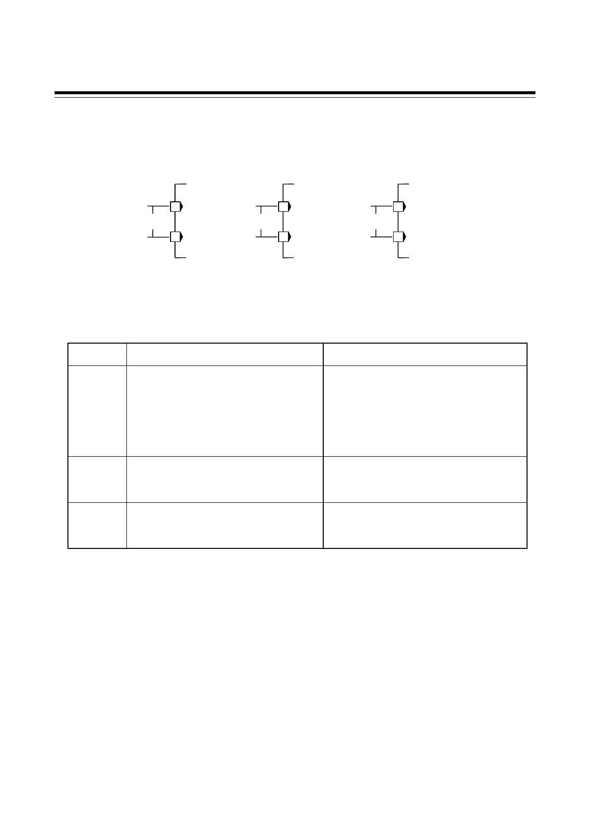
100-240 V AC power
supply type
24 V AC power supply type 24 V DC power supply type
L
N
100-240 V
C
2
1
L
N
24 V
C
2
1
24 V
DC
2
1

 Loading...


