3. WIRING
IMR02C15-E4 3-15
3.4
Handling of the Terminal Cover [optional]
When mounting and removing the terminal cover, take the following steps:
When mounting and removing the terminal cover, apply pressure very carefully to
avoid damage to the terminal cover.
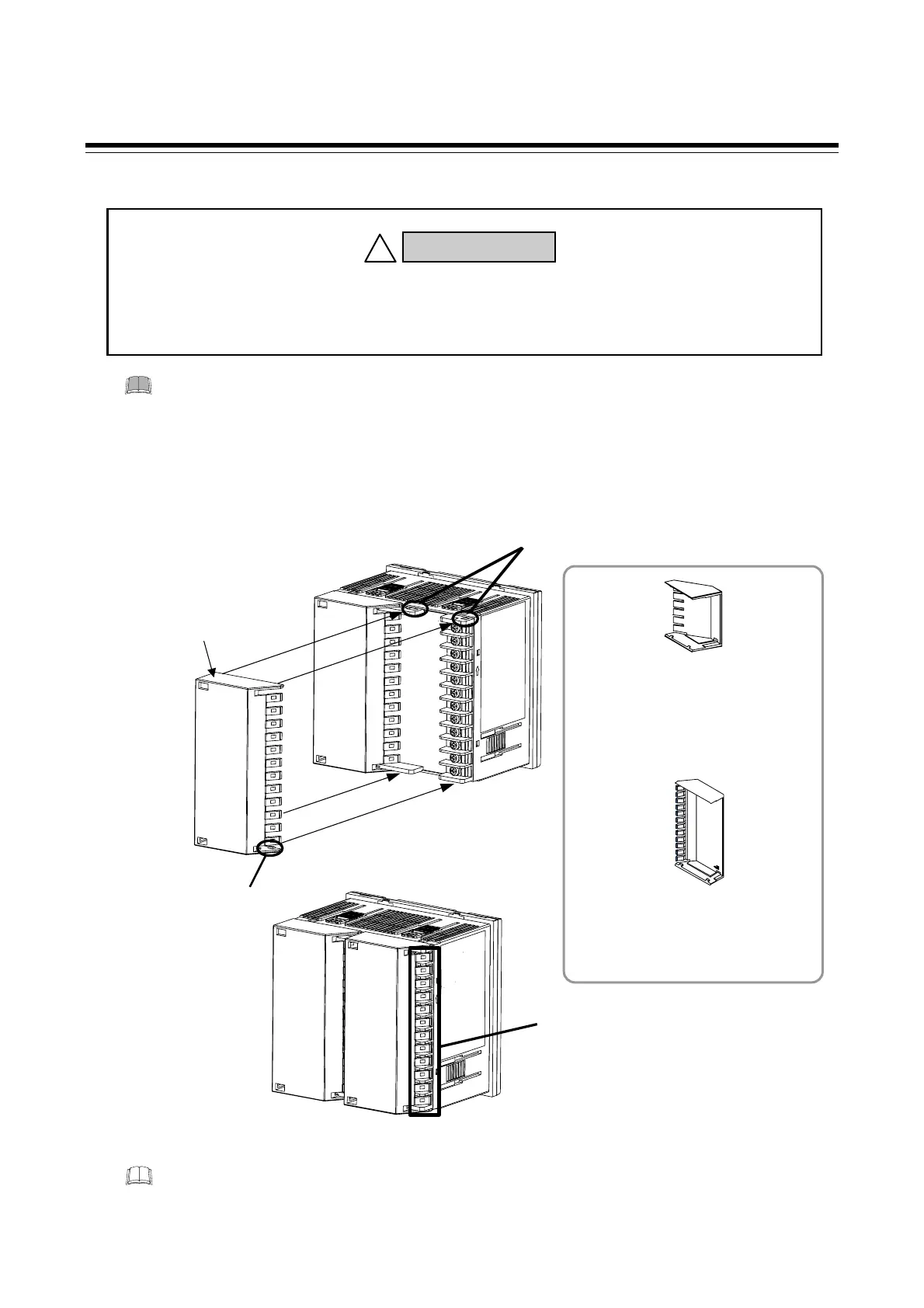
Mounting procedures
1. Check the mounting direction of the terminal cover.
2. Push the protrusions of terminal cover into the insertion slots for mounting the terminal cover.
Insertion slots
Protrusions
Terminal cover
This section of RB400/500/900 terminal
cover can be removed by bending it.
Remove and use it depending on the
wiring condition.
Drawing of RB900 with terminal cover
RB900 is used in the explanatory drawing. The above mounting procedures in the example
shown are the same for RB100, RB400, RB500 and RB700.
RB100 terminal cover
Parts code: KCA100-517 [optional]
RB400/500/900 common terminal cover
Parts code: KFB400-58<1> [optional]
(Two (2) terminal covers may be required
for RB900 depending on specifications.
)
To prevent electric shock or instrument failure, always turn off the power before
mounting or removing the terminal cover.
WARNING
!
RB700
terminal cover
Parts code: KCA700-53 [optional]

 Loading...


