6. OPERATIONS OF THE BASIC FUNCTIONS
IMR02C15-E4
6-7
RUN/STOP transfer state
The table below shows the actual RUN/STOP modes, displays, and STOP lamp states under different
combinations of settings by key operation, communication, digital input (DI), and STOP by the timer
function.
RUN/STOP mode
from key operation
or communication
RUN/STOP mode
by digital input (DI)
STOP by
the Timer
function
Actual
RUN/STOP
mode state
STOP
lamp state
State of
STOP
(character)
Contact closed (RUN) RUN RUN Turns off
STOP is not
displayed
RUN
Contact open (STOP) Lighting
dSTP
Contact closed (RUN) STOP Lighting KSTP
STOP
Contact open (STOP) Lighting
STOP
RUN
Contact closed (RUN) STOP Flashing
TSTP
* When digital input (DI) is used for transfer, the new state is not backed up to EEPROM.
STOP character display
The display location (SV display or PV display) and display/no display setting of the STOP
display can be changed in STOP display selection (F30) of the Engineering mode.
(P. 8-97)
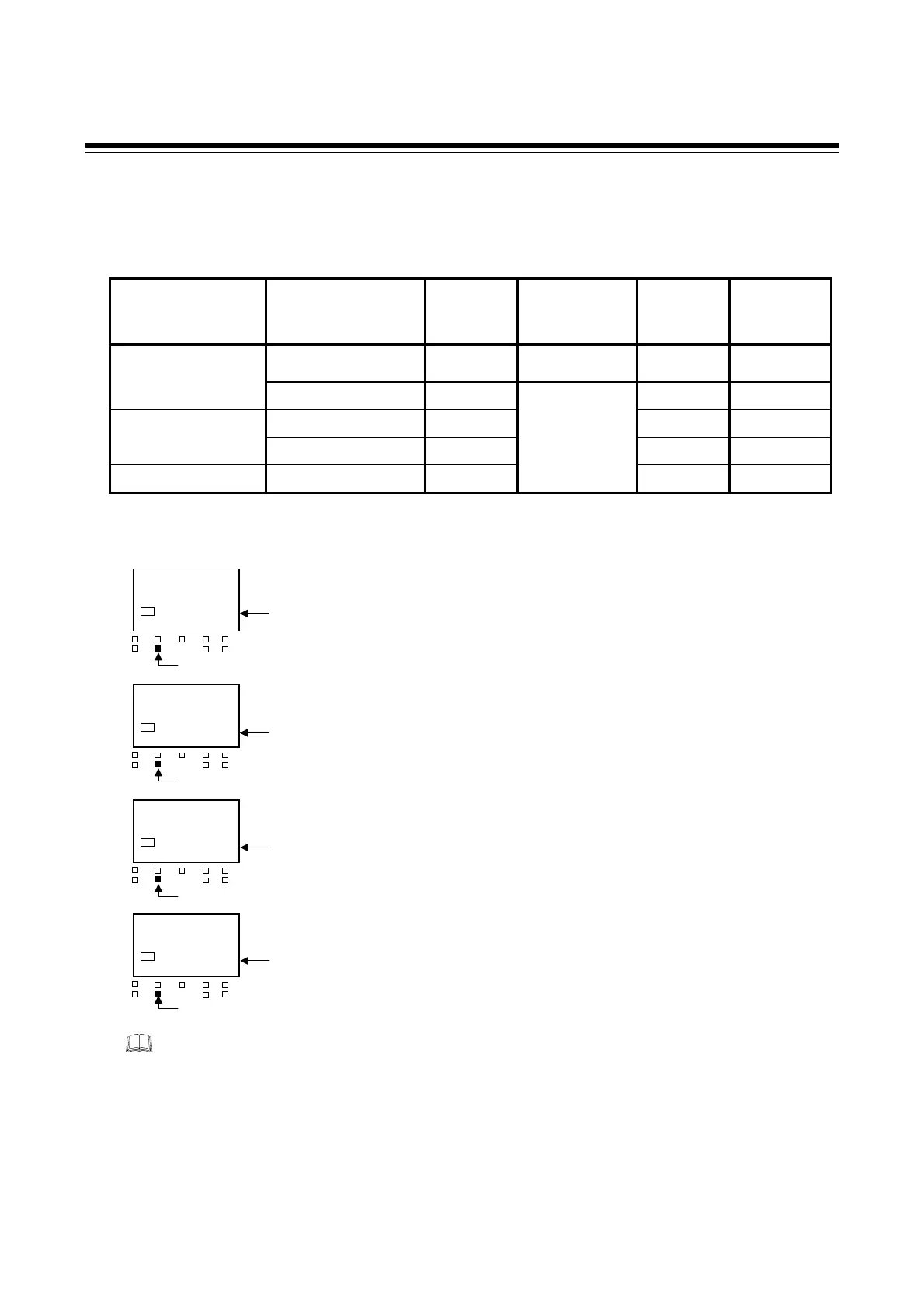
Display when STOP mode is changed by key operation or communication
[When there is RUN/STOP transfer by the digital input (DI)]
28
STOP
SV1
OUT1
OUT
T
DO1 DO
MAN
STOP
DO3
DO4
Display when STOP mode is changed by key operation or communication
[When there is no RUN/STOP transfer by the digital input (DI)]
Display when STOP mode is selected by the digital input (DI)
Display when stopped by the Timer function
28
KSTP
SV1
OUT1
OUT
T
DO1 DO
MAN
STOP
DO3
DO4
28
dSTP
SV1
OUT1
OUT
T
DO1 DO
MAN
STOP
DO3
DO4
28
TSTP
SV1
OUT1
OUT
T
DO1 DO
MAN
STOP
DO3
DO4
STOP lamp lights
STOP lamp lights
STOP lamp lights
STOP lamp flashing

 Loading...


