Roche Diagnostics
Operator’s Manual · Version 3.4 A-43
Cedex Bio analyzer 3Hardware
Main components
Main components
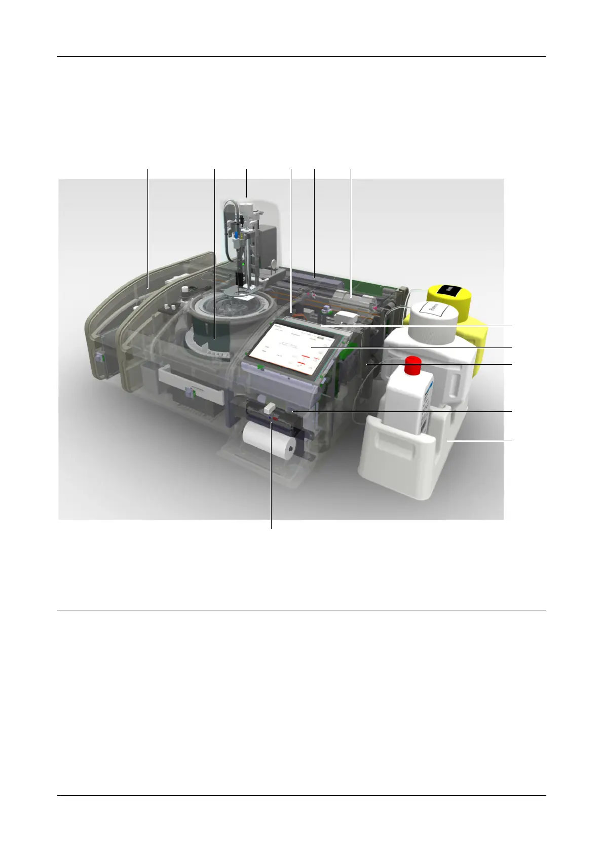
The following figure illustrates the main components of the Cedex Bio analyzer.
Rotor Provides a cooled area for reagents (cooling assembly) and a heated channel for
cuvettes. It moves the containers to the correct position for loading, removal,
pipetting, and measuring.
Transfer unit Pipettes sample, reagent, and other fluids from their source to target containers such
as cuvettes or the rinse station.
Photometer unit Contains the absorbance photometer used for making absorbance measurements.
PCB main board Controls the analyzer hardware.
A ISE unit
B Rotor
C Transfer unit
D Photometer unit
E PCB main board
F Degasser
G Sample area
H Display
I Syringe assembly
J Front USB port
K External fluid rack
L Printer
Figure A-10 Main hardware components