Rockwell Automation Publication ICSTT-RM448M-EN-P - February 2021 33
Chapter 2 The AADvance Safety Controller
notifies the controller accordingly. This acts as an interlock device and helps
prevent the module from going on-line when it is not in the locked position.
Field Wiring
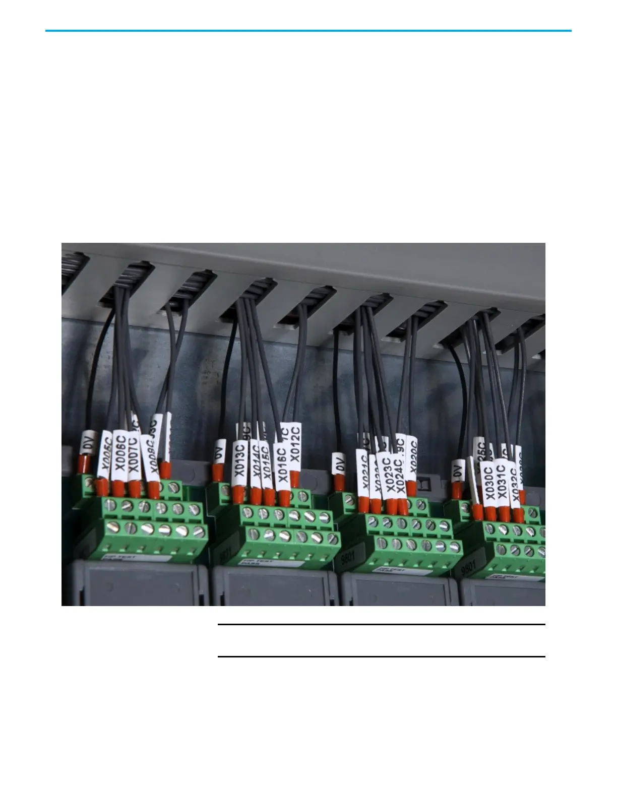
Field device wiring connections are made to industry-standard screw terminal
blocks on the termination assemblies. Terminals are easy to access without
needing to dismantle assemblies. The specification for the field wiring sizes is
given in the topic "Power and External Connector Wiring Requirements".
This illustration shows field wiring connections at the termination assemblies.
Figure 5 - Field Wiring Connections
Processor Base Unit
A processor base unit holds up to three processor modules:
NOTE The recommended torque for termination assembly screw
connectors is 5 Nm.

 Loading...


