Rockwell Automation Publication ICSTT-RM448M-EN-P - February 2021 77
Chapter 5 Install the AADvance System
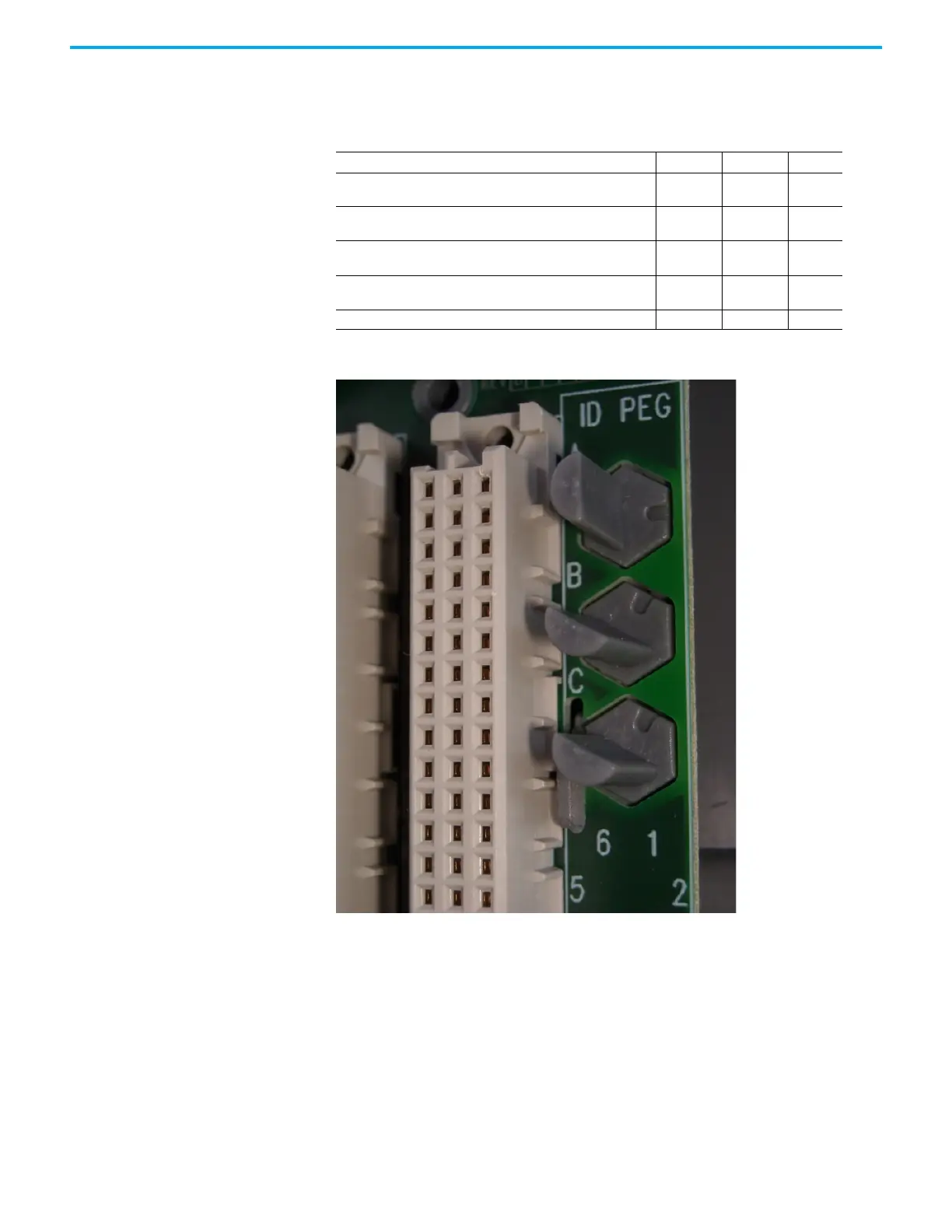
Allocations of Coding Pegs
Coding pegs are assigned to each module type as shown in the following table:
This example shows pins set to positions 2, 1, 1 for a T9401 digital input module.
Connect the AC Safety
Ground Connection
The T9100 processor base unit has a ground stud which must be connected to
the AC safety ground. Connect the ground stud to the AC safety ground bus-
bar of the system or panel.
• Conductor wire must be a minimum of 12 AWG (3.31 mm2) with a
temperature rating of 85 ºC.
•Use a M6 lug on the end of the ground wire.
•Place the lug below the second nut on the ground stud, between two
washers, and use two 10mm wrenches to tighten the nuts to a torque of
1.2 Nm to 2 Nm (0.88 lb./ft. to 1.48 lb./ft.).
Application Key A Key B Key C
T9100 processor base unit
(for T9110 processor module)
111
T9801/2/3 digital input termination assemblies
(for digital input modules)
21 1
T9831/2/3 analogue input termination assemblies
(for analogue input modules)
21 3
T9851/2 digital output termination assemblies
(for digital output modules)
31 1
T9842/1 analogue output module 3 1 2

 Loading...


