EasyManuals Logo

Rockwell Automation Allen-Bradley AADvance T9110 System Build Manual

Rockwell Automation Allen-Bradley AADvance T9110
150 pages
To Next Page IconTo Next Page
To Previous Page IconTo Previous Page
Page #78 background imageLoading...
Page #78 background image
78 Rockwell Automation Publication ICSTT-RM448M-EN-P - February 2021
Chapter 5 Install the AADvance System
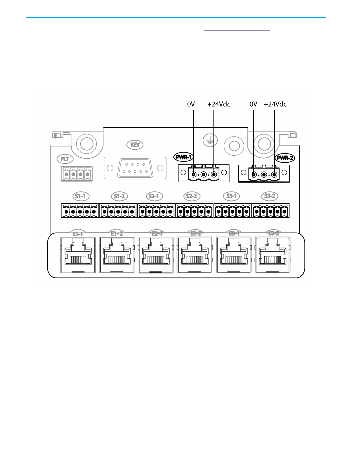
Refer to the photograph of the 24 Vdc Power Connectors the earth stud is
shown between the two power leads.
Connect the 24 Vdc System
Power to an AADvance
Controller
The dual redundant +24 Vdc system power, taken from the chosen power
source, is connected to the controller at two plugs labeled PWR-1 and PWR-2
on the processor base unit:
The processor base unit has a link between the +24 Vdc connections to the
center terminal of each connector PWR-1 and PWR-2. This link may be useful
to connect the +24 Vdc supply to further devices:

Table of Contents

Other manuals for Rockwell Automation Allen-Bradley AADvance T9110

Questions and Answers:

Question and Answer IconNeed help?

Do you have a question about the Rockwell Automation Allen-Bradley AADvance T9110 and is the answer not in the manual?

Rockwell Automation Allen-Bradley AADvance T9110 Specifications

General IconGeneral
BrandRockwell Automation
ModelAllen-Bradley AADvance T9110
CategoryController
LanguageEnglish

Related product manuals