Rockwell Automation Publication ICSTT-RM448M-EN-P - February 2021 35
Chapter 2 The AADvance Safety Controller
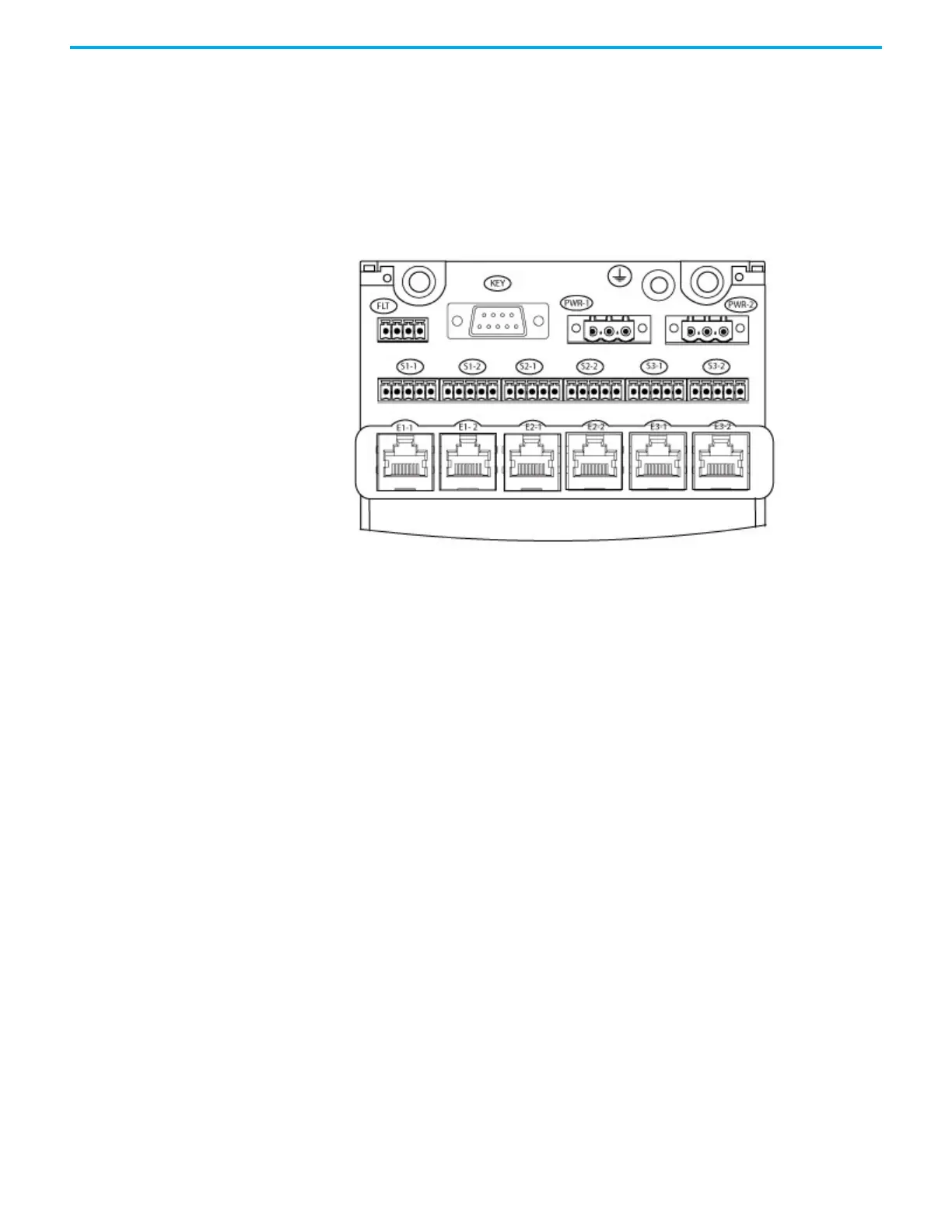
• Earthing Stud
• Ethernet Ports (E1-1 to E3-2)
• Serial Ports (S1-1 to S3-2)
• Redundant +24 Vdc powers supply (PWR-1 and PWR-2)
• Program Enable security key (KEY)
• The FLT connector (currently not used).
Figure 6 - External Connectors on the Processor Base Unit
The power connections supply all three modules with redundant power, each
processor module each have two Serial ports and two Ethernet port
connectors. The KEY connector supports all three processor modules and helps
prevent access to the application unless the Program Enable key is inserted.
Serial Communications Ports
The serial ports (S1-1 and S1-2; S2-1 and S2-2; S3-1 and S3-2) support the
following signal modes depending on use:
• RS485fd: A four-wire full duplex connection that features different
busses for transmit and receive. This selection must also be used when
the controller is acting as a MODBUS Master using the optional four-
wire definition specified in Section 3.3.3 of the MODBUS-over-serial
standard.
• RS485fdmux: A four-wire full-duplex connection with tri-state outputs
on the transmit connections. This must be used when the controller is
acting as a MODBUS Slave on a four-wire bus.
• RS485hdmux: A two-wire half duplex connection applicable for master
slave or slave use. This is shown in the MODBUS-over-serial standard.
Processor Back-up Battery
The T9110 processor module has a back-up battery that powers its internal Real
Time Clock (RTC) and a part of the volatile memory (RAM). The battery only
supplies power when the processor module is no longer powered from the

 Loading...


