118 Rockwell Automation Publication ICSTT-RM448M-EN-P - February 2021
Chapter 6 System Startup
I/O Module Startup Process The startup sequence is different when a module is installed into an on-line
system that is running compared to installing the module into a system that is
off-line and has processor modules but no I/O modules installed.
Force Off to GREEN
Aux Depends on application
Serial 1 Depends on data Connection
Serial 2 Depends on data Connection
Ethernet 1 Depends on data Connection
3. To insert a 3rd processor module repeat step 1 and insert in slot C.
Table 13 - Procedure for Installation of a Second and Third Processor
Step Task
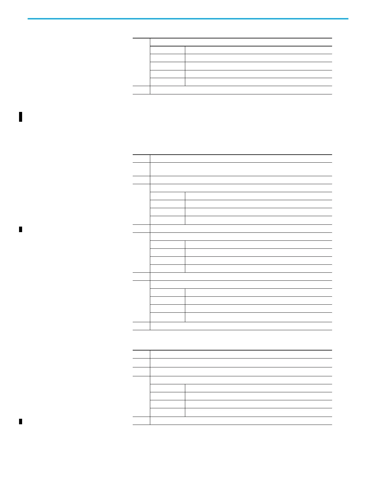
Table 14 - Single Module or First Module of a group Installation Procedure
Step Task
1.
This procedure applies to a single module installation or the first module of a redundant group
installation.
2 Install the I/O module and turn the locking screw to the lock position.
3.
The input module will show the following status indications:
Healthy GREEN
Ready RED
Run RED
Channel 1 – 8 Off
4. The input module will follow its startup sequence and the module will educate.
5.
After approximately 3 seconds the module will now show the following status indications:
Healthy GREEN
Ready GREEN
Run AMBER
Channel 1 – 8 Off
6. Push the Fault Reset button on the processor module and the Run indication goes GREEN.
7.
The module will now be on-line with the following status indications:
Healthy GREEN
Ready GREEN
Run GREEN
Channel 1 – 8 Dependent on channel status
8. If the module fails to educate (and go on-line) replace the module.
Table 15 - Second or third Module of a Group Installation Procedure
Step Task
1. This procedure applies to a second or third module of a redundant group installation.
2 Install the Input/Output Module and turn the locking screw to the lock position.
3.
The module will provide the following status indications:
Healthy GREEN
Ready RED
Run RED
Channel 1 – 8 Off
4. The input module will follow its startup sequence and the module will educate.

 Loading...


