EasyManuals Logo

Rockwell Automation Allen-Bradley AADvance T9110 System Build Manual

Rockwell Automation Allen-Bradley AADvance T9110
150 pages
To Next Page IconTo Next Page
To Previous Page IconTo Previous Page
Page #79 background imageLoading...
Page #79 background image
Rockwell Automation Publication ICSTT-RM448M-EN-P - February 2021 79
Chapter 5 Install the AADvance System
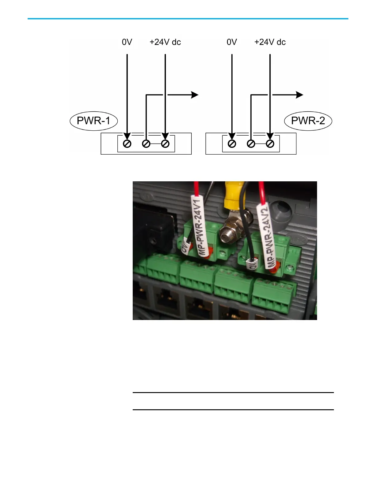
24 Vdc Power Connectors
For each power supply connection, do the following:
Connect the negative line from the power supply, typically labeled '0 V',
to the left-hand terminal.
Connect the positive line from the power supply, typically labeled '+24 V',
to the right-hand terminal.
Apply a minimum tightening torque of 0.5 Nm (0.37 ft. lb.) to the
terminal screws.
Procedure to Connect Serial
Communications Cabling
The serial ports (S1-1 and S1-2; S2-1 and S2-2; S3-1 and S3-2) support the
following signal modes depending on use:
IMPORTANT
Make sure that PWR-1 and PWR-2 are supplied from independent
24 Vdc sources.

Table of Contents

Other manuals for Rockwell Automation Allen-Bradley AADvance T9110

Questions and Answers:

Question and Answer IconNeed help?

Do you have a question about the Rockwell Automation Allen-Bradley AADvance T9110 and is the answer not in the manual?

Rockwell Automation Allen-Bradley AADvance T9110 Specifications

General IconGeneral
BrandRockwell Automation
ModelAllen-Bradley AADvance T9110
CategoryController
LanguageEnglish

Related product manuals