76 Rockwell Automation Publication ICSTT-RM448M-EN-P - February 2021
Chapter 5 Install the AADvance System
• Insert the retaining clip on the back of the termination assembly into
the slot on the I/O base unit. Press the termination assembly onto the
base unit and then slide the assembly upwards as far as it will go.
• Make sure the retaining tab clips over the printed circuit board to
secure the termination assembly in position.
2. Check coding pegs.
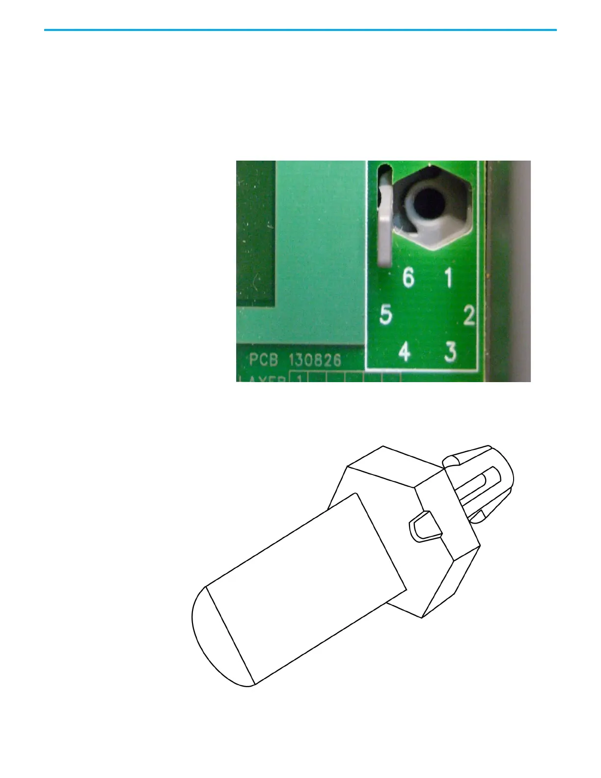
• Observe the legend on the T9100 processor base unit (and repeated on
some termination assemblies) which defines the six possible positions
for a coding peg. The positions are numbered from 1 to 6.
•Examine a coding peg (fitted) and identify the index recess on the
hexagonal flange.
• Refer to the following table and verify each coding peg is fitted so its
index recess is adjacent to the relevant numbered position.

 Loading...


