EasyManuals Logo

Rockwell Automation Allen-Bradley AADvance T9110 System Build Manual

Rockwell Automation Allen-Bradley AADvance T9110
150 pages
To Next Page IconTo Next Page
To Previous Page IconTo Previous Page
Page #59 background imageLoading...
Page #59 background image
Rockwell Automation Publication ICSTT-RM448M-EN-P - February 2021 59
Chapter 4 Before You Begin
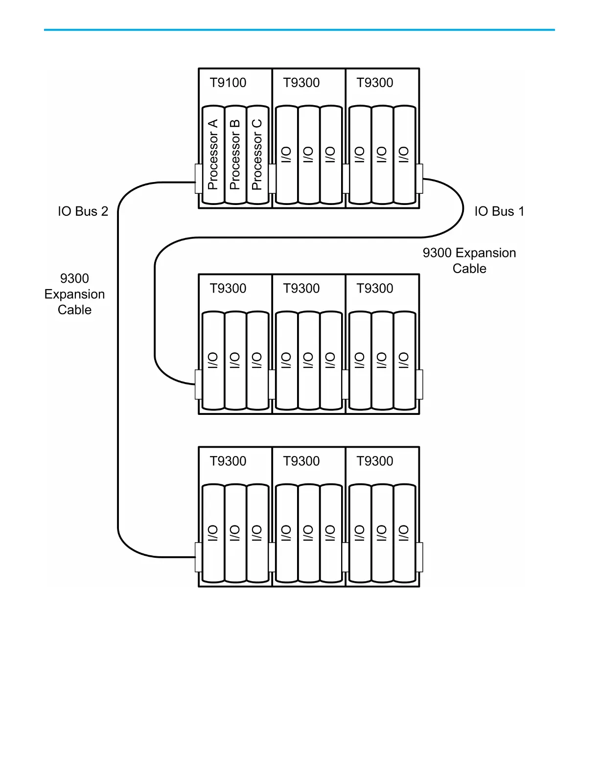
Figure 12 - Connecting Base Units with Expansion Cables
The expansion bus accessed from the right hand edge of the T9100 processor
base unit is designated I/O Bus 1, while the bus accessed from the left hand
edge is designated I/O Bus 2. The module positions (slots) in the I/O base units
are numbered from 01 to 24, the left most position being slot 01. Any individual
module position within the controller can thus be uniquely identified by the
combination of its bus and slot numbers, for example 1-01.

Table of Contents

Other manuals for Rockwell Automation Allen-Bradley AADvance T9110

Questions and Answers:

Question and Answer IconNeed help?

Do you have a question about the Rockwell Automation Allen-Bradley AADvance T9110 and is the answer not in the manual?

Rockwell Automation Allen-Bradley AADvance T9110 Specifications

General IconGeneral
BrandRockwell Automation
ModelAllen-Bradley AADvance T9110
CategoryController
LanguageEnglish

Related product manuals