Troubleshooting 10-25
1560D-UM051D-EN-P – February 2005
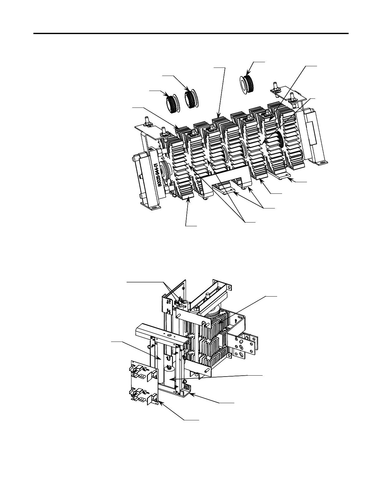
Figure 10.17 – 2300V Heatsink Module, 600A
Figure 10.16 – Removing and Replacing SCR1, SCR2 and SCR5
Snubber Resistors
Heatsink Assembly
Frame Assembly
Gate Driver Board
Sharing Resistor
Snubber Capacitor
Snubber Resistors
Heatsink Assembly
Frame Assembly
Gate Driver Board
Sharing Resistor
Snubber Capacitor
To Remove SCR1:
• Remove shorting bar hardware
• Pry Heatsinks 1 and 2 apart
• Extract SCR
To Insert New SCR:
• Apply thin film of electrical joint compound
to surfaces of SCR
• Install SCR so that it is seated in locating
pin of heatsink (note orientation of SCR).
• Pry heatsinks to close gap, ensuring that
SCR is seated properly in both its locating
pins.
• Rotate SCR so that all leads have same
direction.
Proceed to replacement of other SCRs in
the matched set (SCR2 and SCR5).
Note: You must replace all three SCRs
of a matched set.
Heatsink 6
Heatsink 1
Locating Pins
SCR5
Locating Pin
Heatsink 5
Heatsink 2
SCR1
SCR2
Heatsink 3
Shorting Bars
Shorting Bar
 Loading...


