Installation 2-7
1560D-UM051D-EN-P – February 2005
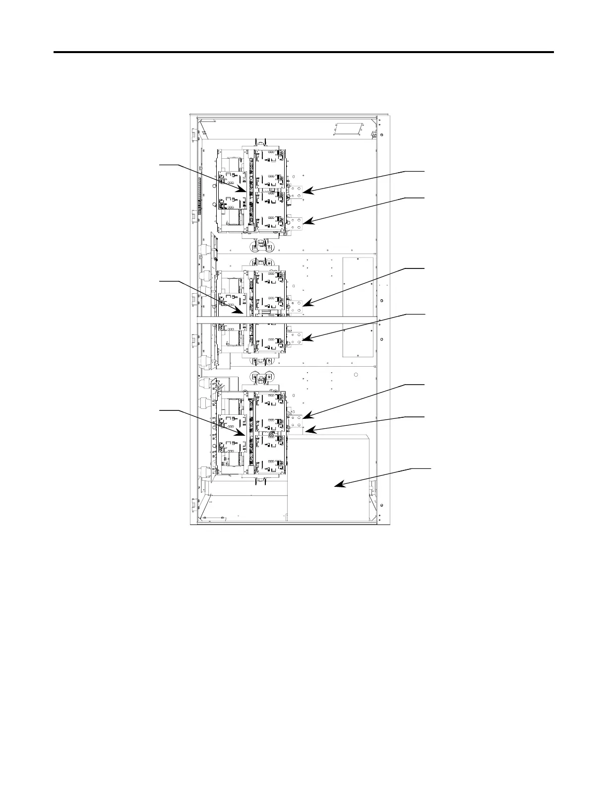
Phase 1 Module
Phase 1 Line Terminal
Phase 1 Load Terminal
Phase 2 Module
Phase 3 Module
Phase 2 Line Terminal
Phase 2 Load Terminal
Phase 3 Line Terminal
Phase 3 Load Terminal
(Not visible this view)
Bypass Contactor
Phase 1 Module
Phase 1 Line Terminal
Phase 1 Load Terminal
Phase 2 Module
Phase 3 Module
Phase 2 Line Terminal
Phase 2 Load Terminal
Phase 3 Line Terminal
Phase 3 Load Terminal
(Not visible this view)
Bypass Contactor
Figure 2.3 – Power Connections • 1560D – 600 A, 2400 V to 6900 V
Important: For retrofit units (Bul. 1560D), the CEC and NEC require that
branch-circuit protection of the AC line input to the controller be provided
by a circuit breaker or motor starter. This function is included with a
Bulletin 1562D.
Important: The control and signal wires should be positioned at least
six (6) inches (150 mm) from power cables. Additional noise suppression
practices (including separate steel conduits for signal leads, etc.) are
recommended.
 Loading...


