Publication 2094-UM001A-EN-P — September 2006
136 Configure and Startup the Kinetix 6000 Drive System
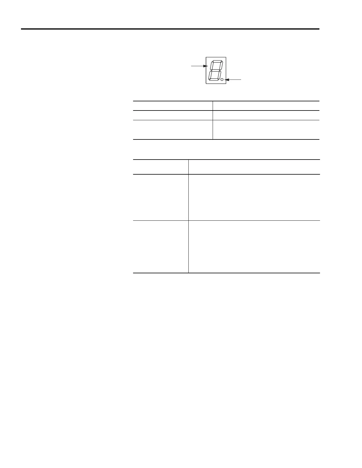
3. Observe the IAM/AM logic power LED indicator.
4. Determine your source of three-phase input power.
Seven-segment
Fault Status LED Indicator
Logic Power
LED Indicator
If the Logic Power LED Indicator is Then
ON Go to Step 4.
Not ON
1. Check your control power connections.
2. Go back to main Step 2.
If Your Three-phase
Power
Then
Is sourced from a LIM
1. Set CB1 to the ON position.
2. Verify the Hardware Enable Input signal (IOD pin 2) for each
axis is at 0 volts.
Remove the connection between IOD-1 and IOD-2 if one exists.
3. Go to main Step 5.
Is not sourced from a LIM
1. Apply 195...265V ac (230V) or 324...528V ac (460V) input power
to the IAM (IPD connector).
2. Verify the Hardware Enable Input signal (IOD pin 2) for each
axis is at 0 volts.
Remove the connection between IOD-1 and IOD-2 if one exists.
3. Go to main Step 5.

 Loading...


