Publication 2094-UM001A-EN-P — September 2006
Configure and Startup the Kinetix 6000 Drive System 137
5. Observe the IAM/AM fault status LED indicator.
The status LED indicator will first flash the SERCOS node address,
then cycle through phases until final configuration (phase 4) is
reached.
6. Observe the three status LED indicators on the front of the IAM/
AM.
7. Observe the three SERCOS LED indicators on the SERCOS module.
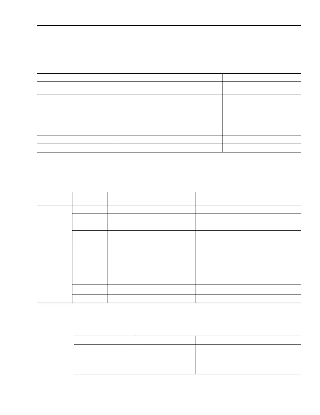
IAM/AM Fault Status LED Indicator Status Do This
Actively cycling (phase 0)
The drive is looking for a closed SERCOS ring. Wait for
phase 1 or take corrective action until you reach phase 1.
Check fiber-optic connections.
Displaying a fixed 1 (phase 1)
The drive is looking for active nodes. Wait for phase 2 or
take corrective action until you reach phase 2.
Check node addressing.
Displaying a fixed 2 (phase 2)
The drive is configuring nodes for communication. Wait for
phase 3 or take corrective action until you reach phase 3.
Check program motor and drive
configuration against installed hardware.
Displaying a fixed 3 (phase 3)
The drive is configuring device specific parameters. Wait for
phase 4 or take corrective action until you reach phase 4.
Check motor catalog number against
selection.
(1)
Displaying a fixed 4 (phase 4) The drive is configured and active. Go to Step 6.
Flashing an E followed by two numbers Drive is faulted. Go to Error Codes on page 146.
(1)
You can get diagnostic information from the module by highlighting the module name in RSLogix 5000 software. A Pseudo Key Failure often indicates that the motor
selection does not match the motor installed.
Status LED
Indicator
Condition Status Do This
Drive
Off Normal condition Observe the Comm Status LED indicator.
Steady red Drive is faulted Go to IAM/AM Status Indicators on page 152.
Comm
Flashing green Establishing communication with network Wait for steady green.
Steady green Communication is ready Observe the Bus Status LED indicator.
Off No ring present Go to IAM/AM Status Indicators on page 152.
Bus
Steady green Axis is enabled when status should be disabled
1. Verify Hardware Enable Input (IOD-2) is open.
2. Verify MSO instruction is not commanded in RSLogix
5000 software.
3. Return to Apply Power to the Kinetix 6000 Drive on page
135.
Flashing green
(1)
Bus is up, axis is disabled (normal status) Go to Step 7.
Off DC bus is not present Go to IAM/AM Status Indicators on page 152.
(1)
The follower IAM has a 2.5 second delay after dc bus voltage is applied before the Bus Status LED begins flashing. This provides the common bus leader time to complete
pre-charge.
Three SERCOS LED Indicators Status Do This
Flashing green and red Establishing communication Wait for steady green on all three LED indicators.
Steady green Communication ready Go to Test and Tune the Axes.
Not flashing green and red/
not steady green
SERCOS module is faulted
Go to the appropriate Logix manual for specific instructions
and troubleshooting.

 Loading...


