Rockwell Automation Publication 2099-UM001G-EN-P - December 2022 65
Kinetix 7000 Connector Data Chapter 3
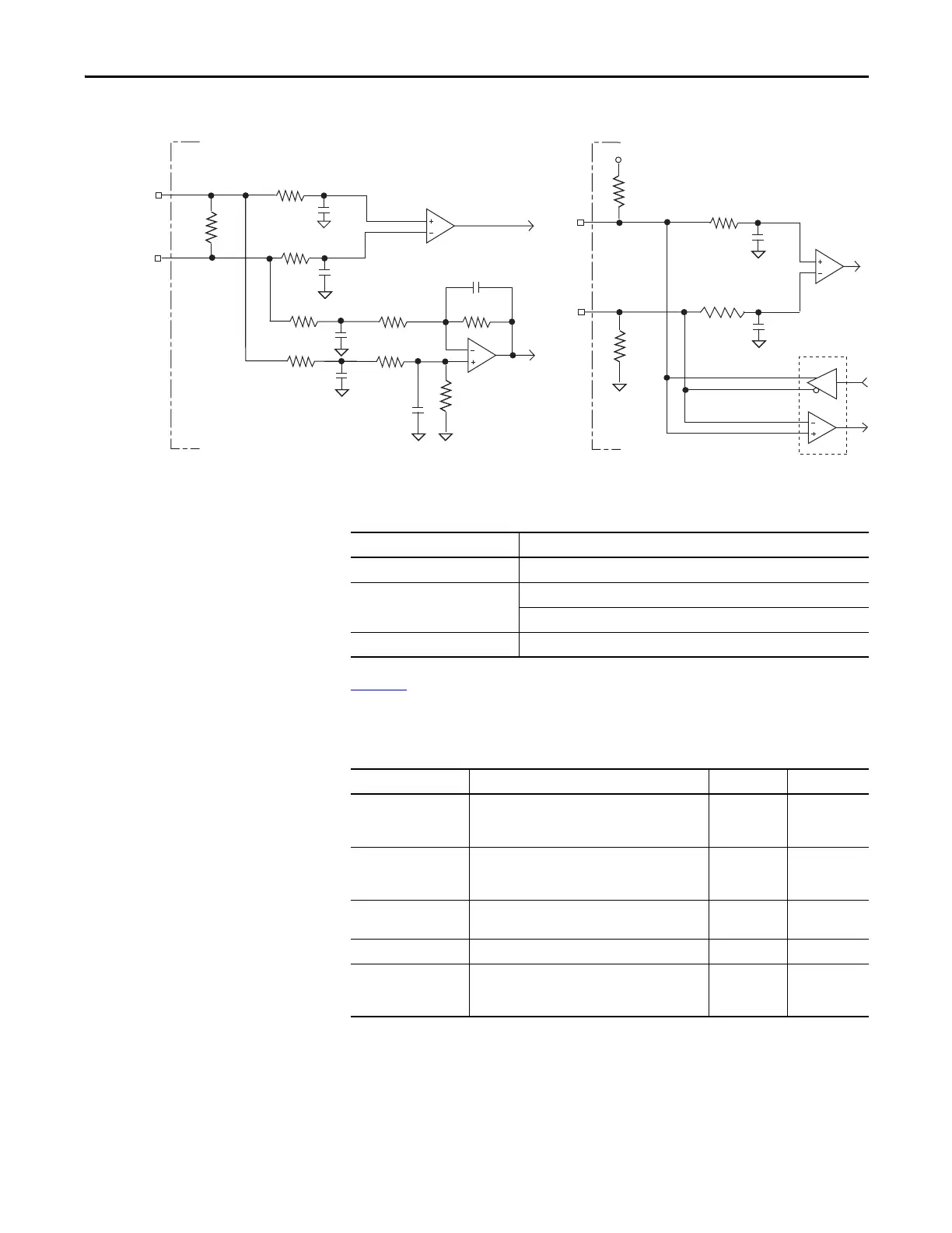
Figure 42 - AM, BM, and IM Motor Encoder Inputs
Table 26 - Motor Encoder Feedback Specifications
Tabl e 27 provides a description of the AM, BM, and IM inputs for TTL
encoders.
Table 27 - TTL Encoder Specifications
+5 V
+
-
56 pF
56 pF
10k Ω
1k Ω
1k Ω
100 pF
+
-
100 pF
56 pF
56 pF
1k Ω
1k Ω
1k Ω
1k Ω
1kΩ
56 pF
56 pF
10k Ω
10k Ω
10k Ω
1k Ω
1k Ω
AM and BM Channel Inputs
IM Channel Input
Drive Drive
Attribute Value
Encoder Types Incremental, A quad B, Sine/Cosine, Intelligent, and Absolute
Maximum Input Frequency 5.0 MHz (TTL input) per channel
250 kHz (Sine/Cosine input)
Commutation Feedback Hall sensor
Parameter Description Minimum Maximum
AM, BM, and IM
ON-state
Input Voltage
Input voltage difference between the + input and
the - input that is detected as an ON-state.
+1.0V +7.0V
AM, BM, and IM
OFF-state
Input Voltage
Input voltage difference between the + input and
the - input that is detected as an OFF-state.
-1.0V -7.0V
Common Mode
Input Voltage
Potential difference between any encoder signal and
logic ground.
-7.0V +12.0V
DC Current Draw Current draw into the + or - input. -30 mA 30 mA
AM, BM Input
Signal Frequency
Frequency of the AM or BM signal inputs. The count
frequency is 4 times this frequency, since the circuitry
counts all four transitions.
—5.0 MHz

 Loading...


