Rockwell Automation Publication 1734-UM013J-EN-P - July 2014 101
Configure the Module in a GuardLogix Controller System Chapter 5
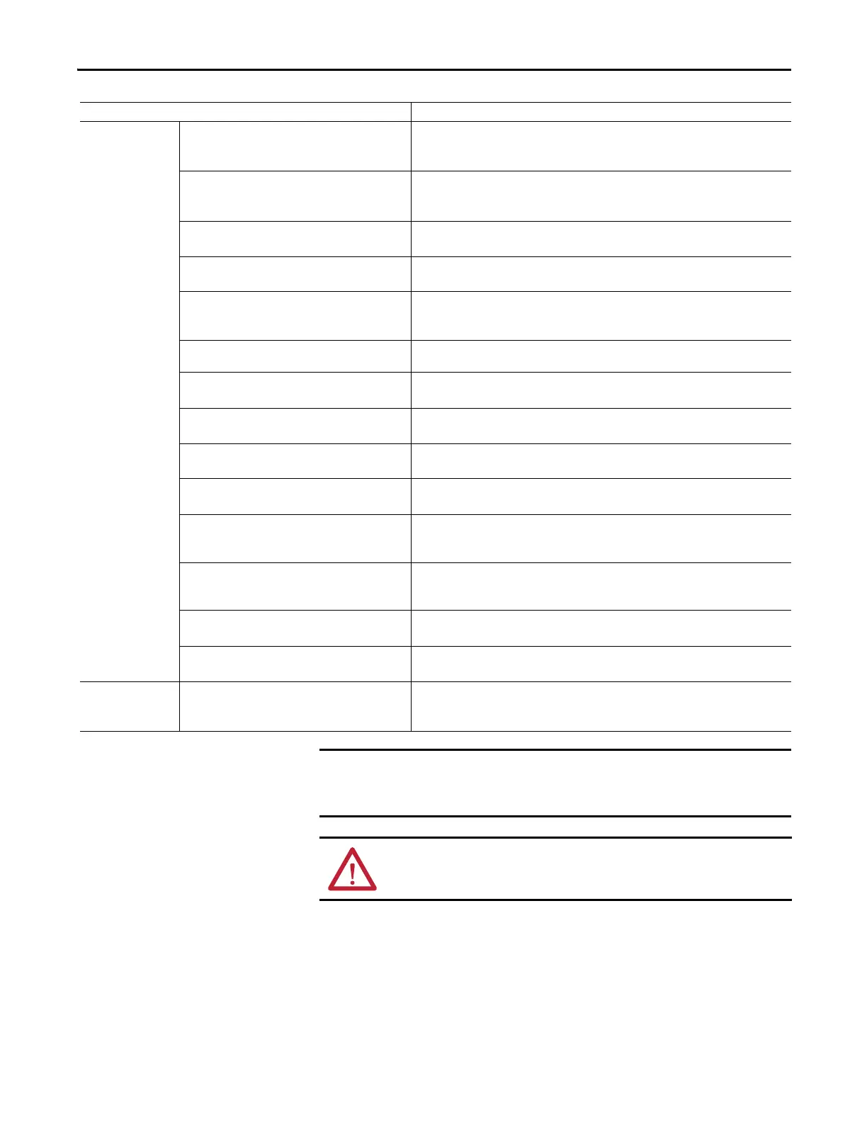
Analog Input Data
Run Mode
STANDARD
Indicates whether consumed data is actively being updated by a device that is in one of these
states:
• Run mode: 1 Idle State: 0
Connection Faulted
STANDARD
Indicates the validity of the safety connection between the safety producer and the safety
consumer.
• Valid: 0 Faulted: 1
Safety Input Data
SAFETY
Value of analog input data
Individual Safety Input Status
SAFETY
Indicates the status of each safety input circuit.
Normal: 1 Fault (Alarm): 0
Individual Status - Process Alarms
STANDARD
Indicates whether each channel's Safety Input Data value is between the configured High and
Low Alarm values.
Normal: 1 Alarm: 0
Individual Status - Fault Reason
STANDARD
Input Point Fault Reason
Individual HH Alarm Status
STANDARD
Individual High High Alarm Status
Normal: 1 Alarm: 0
Individual H Alarm Status
STANDARD
Individual High Alarm Status
Normal: 1 Alarm: 0
Individual L Alarm Status
STANDARD
Individual Low Alarm Status
Normal: 1 Alarm: 0
Individual LL Alarm Status
STANDARD
Individual Low Low Alarm Status
Normal: 1 Alarm: 0
Individual Tachometer Overfrequency
SAFETY
When the input is configured for Tachometer mode, this data indicates an overfrequency
condition; that is, when pulses are faster than 1000 Hz.
Normal: 1 Fault: 0
Individual Tachometer Under-frequency
SAFETY
When the input is configured for Tachometer mode, this data indicates a under-frequency
condition; that is, when pulses are slower than 1 Hz.
Normal: 1 Fault: 0
Individual Tachometer Dual Low
SAFETY
Indicates that both channels are low when the input is configured for Tachometer mode.
Normal: 1 Fault: 0
Input Power
STANDARD
Indicates that input power over- or under-range.
Normal: 1 Fault: 0
Analog Output Data Reset Tachometer
SAFETY
Resets a latched overfrequency condition and enables the module to begin calculating frequency
again.
• No reset: 0 Reset: 1
Data Description
In the previous table, ‘SAFETY’ denotes information the controller can use in
safety-related functions. ‘STANDARD’ denotes additional information that
must not be directly used for safety functions.
ATTENTION: Do not rely on data readback to detect faults. You must monitor
status bits to detect faults.

 Loading...


