EasyManuals Logo

Rockwell Automation Allen-Bradley POINT Guard User Manual

Rockwell Automation Allen-Bradley POINT Guard
212 pages
To Next Page IconTo Next Page
To Previous Page IconTo Previous Page
Page #60 background imageLoading...
Page #60 background image
60 Rockwell Automation Publication 1734-UM013J-EN-P - July 2014
Chapter 4 Install the Module
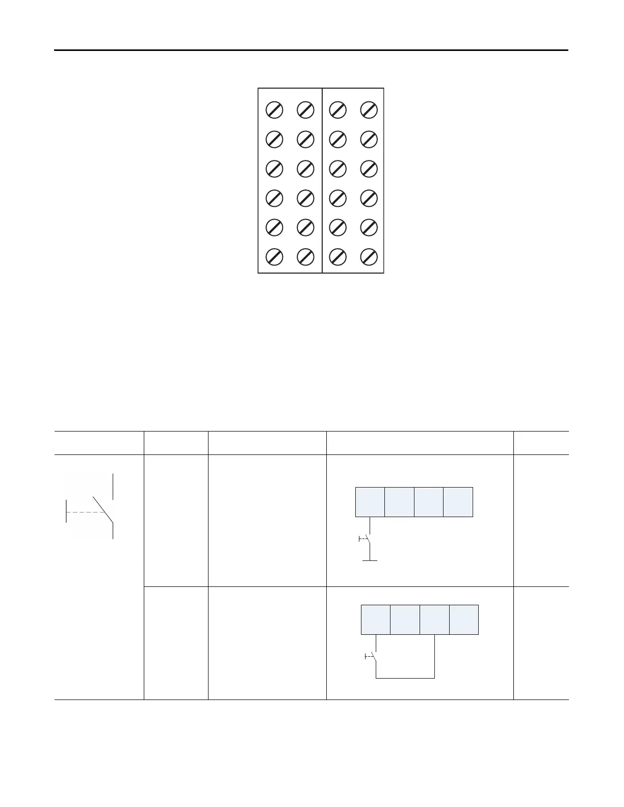
Figure 27 - 1734-IE4S Field Connections
Connection Details
See the tables that show input device connection methods and their safety
categories.
V0 V1 V2 V3
I0 I1 I2 I3
COM COM COM COM
COM COM COM COM
S0 S1 S2 S3
S0 S1 S2 S3
1734-TOP3 Base
Shown
Where:
V0…V3 = Voltage inputs 0…3
I0…I3 = Current inputs 0…3
COM = Supply Common
S0…S3 = Sensor power terminals
Connected Device Test Pulse from
Test Output
Connection Schematic Diagram Safety
Category
Push Button No Connect the push button between 24V
DC and I0.
1
Yes Connect the push button between I0
and T0. T0 must be configured as test
pulse.
2
I0 I1 T0 T1
24V DC
I0 I1 T0 T1

Table of Contents

Questions and Answers:

Question and Answer IconNeed help?

Do you have a question about the Rockwell Automation Allen-Bradley POINT Guard and is the answer not in the manual?

Rockwell Automation Allen-Bradley POINT Guard Specifications

General IconGeneral
BrandRockwell Automation
ModelAllen-Bradley POINT Guard
CategoryI/O Systems
LanguageEnglish

Related product manuals