Rockwell Automation Publication 1734-UM013J-EN-P - July 2014 61
Install the Module Chapter 4
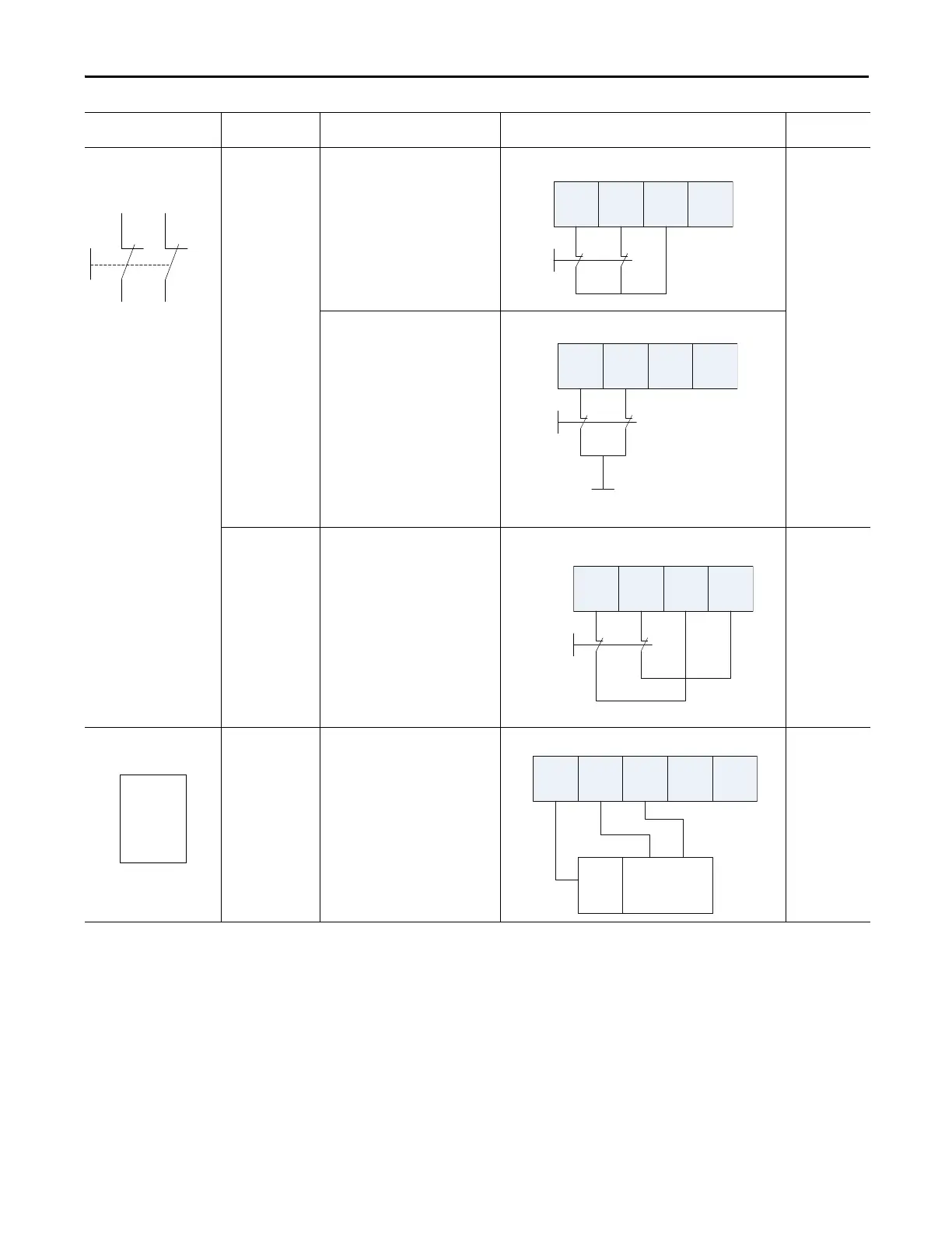
Emergency stop button
Door monitoring switch
No Connect the devices between T0 and I0
and I1, noting that T0 is configured for
24V power supply.
3
Connect the devices between 24V DC
and I0 and I1.
Yes Connect the device between I0 and T0,
and I1 and T1.
4
Light Curtain Yes Connect the OSSD1 and OSSD2 to I0 and
I1, respectively. Connect the 24V power
supply commons.
3 or 4 based on
light curtain
being used
Connected Device Test Pulse from
Test Output
Connection Schematic Diagram Safety
Category
I0 I1 T0 T1
I0 I1 T0 T1
24V DC
I0 I1 T0 T1In -
24V
DC
Com
OSSD2
OSSD1

 Loading...


