Specifications and Site Requirements
Electrical Specifications
Node Controller Hardware User Manual 77
Rockwell Automation Publication MMI-UM013B-EN-P - April 2020
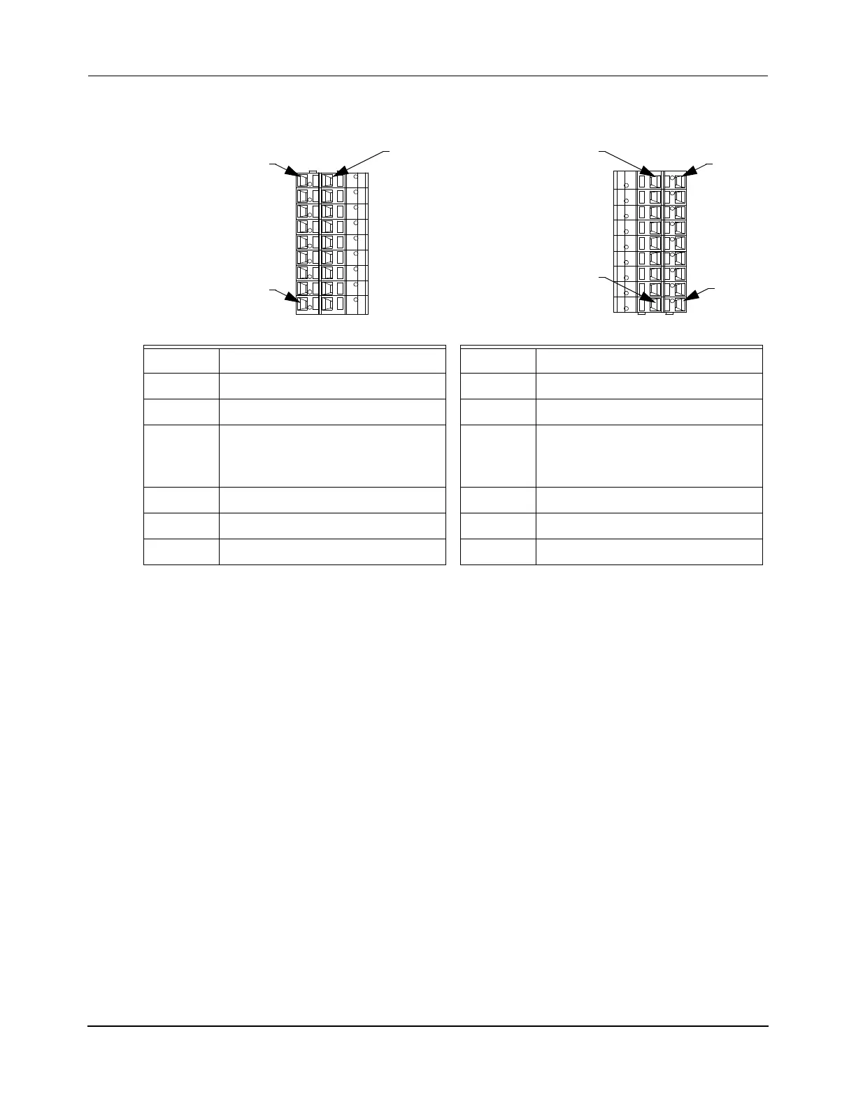
Table 4-22: NC-12 Node Controller Digital I/O Pinout
Cage Clamp – Input
*
* See Figure 3-2 on page 47 for the digital I/O equivalent circuits.
Cage Clamp – Output
*
0 Input 0 Output
1 Input 1 Output
2 Input 2 Output
.
.
.
Inputs repeat for a
total of 16 inputs
.
.
.
Outputs repeat for a
total of 16 outputs
15 Input 15 Output
COM +3–24V DC VDD +5–35V DC
GND
†
† The GND pin is not used for the digital inputs.
—GNDDC RTN

 Loading...


