Introducing the Ruckus Wireless AP
Getting to Know the AP Features
Ruckus Wireless Indoor AP 100.2.0 User Guide, 800-70892-001 Rev A 51
Bottom Panel
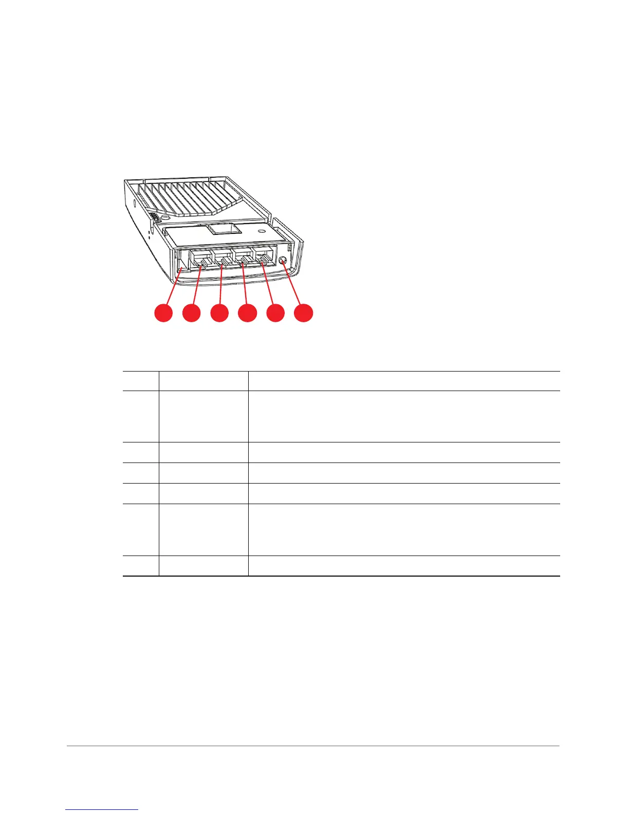
Figure 22 shows the bottom view of the H500. For a description of each bottom
panel part, refer to Ta b le 2 4 .
Figure 22. H500 bottom panel
Table 24. H500 bottom panel elements
No. Item Name Description
1 USB port Optional USB connector (refer to
About Peripheral Devices
and
Appendix A: AP Support for Bluetooth Low Energy
Devices
).
2 LAN4 port 10/100 RJ-45 Ethernet Port.
3 LAN3 port 10/100 RJ-45 Ethernet Port.
4 LAN2 port 10/100 RJ-45 Ethernet Port.
5 LAN1+PoE port 10/100 RJ-45 LAN port with PoE out. Supports 802.3af PSE
Class 2 or 3 (depending on power input; refer to
About
Peripheral Devices
).
6 48VDC port Optional 48VDC power input connector.