Section 8: Appendix
CG4 Series Service Manual Page 8-3
8.1 OPTIONAL ACCESSORIES - CUTTER (cont’d)
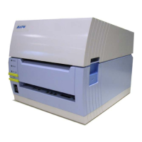
6.
From the base of the Cutter kit, secure the cutter unit to the
printer with the supplied
screw (circled) as shown.
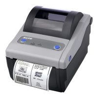
7. Connect the Cutter kit’s cable to the OPTION connector
on the
MAIN PCB.
Route the
Cutter kit’s cable through the groove (circled) of
the printer as shown.
8. Assemble the Bottom Housing cover back to the printer
and secure with the three
screws removed in step 1.
8.1.2 To route the media when the cutter is installed
Loading of the media for cutter unit is similar to the usual procedure as explained in Section 2.3 Loading
Labels
of CG4 Series Operator Manual.
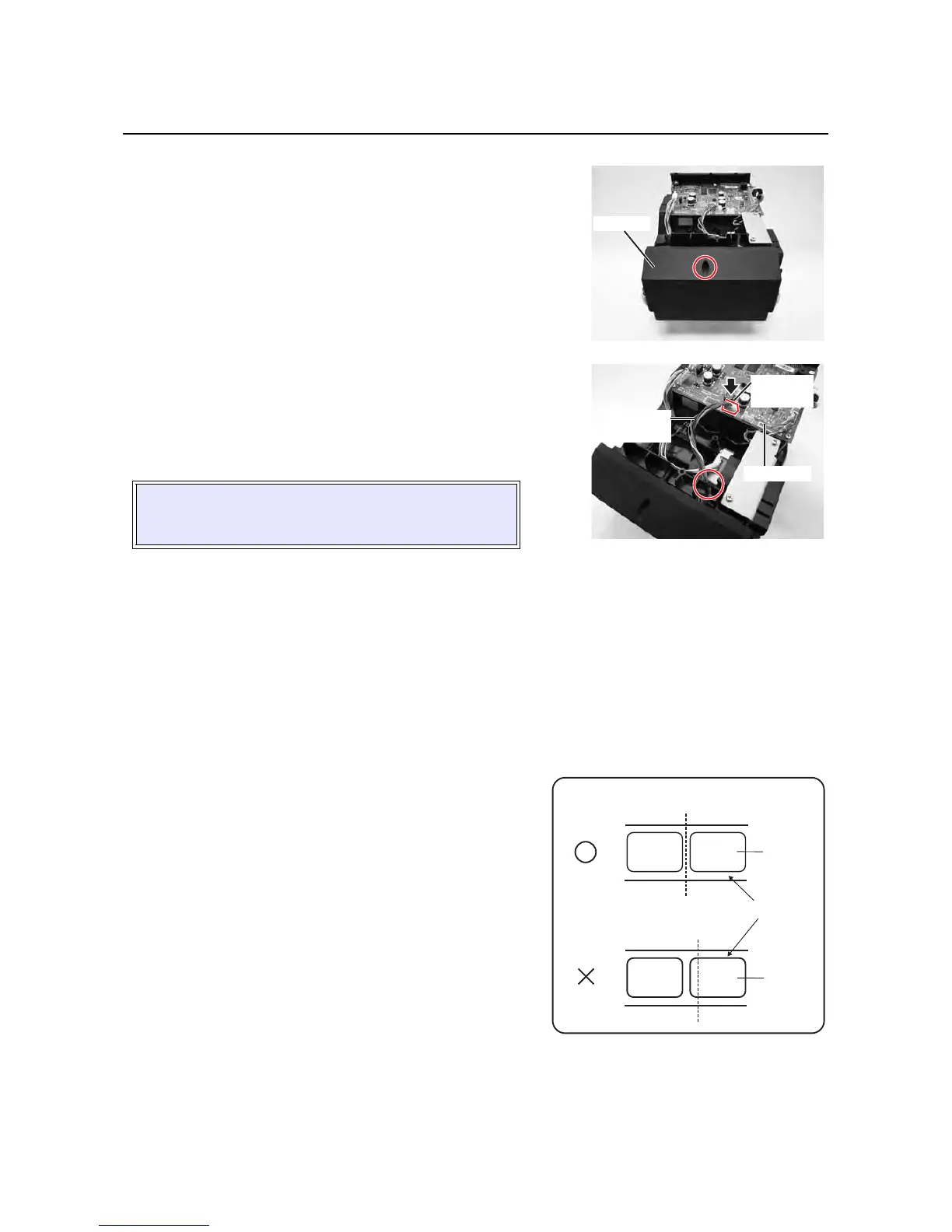
8.1.3 Cut position Adjustment
If the cutting position is not at the regular position as mentioned below, you can change the offset setting
with the SBPL commands. Please refer to
Section 6.6 Offset position Adjustment for the detailed
procedures.
Notes when using media with optional cutter
• Cutting of Labels
The correct cutting position is at the label gap. Cutting
onto the label must be avoided because the label
adhesive that accumulates on the blade will affect cutter
sharpness.
CAUTION:
Ensure that no cables are pinched between parts when
you are assembling the cover.
 Loading...