Section 8: Appendix
Page 8-6
CG4 Series Service Manual
8.2 OPTIONAL ACCESSORIES - DISPENSER (cont’d)
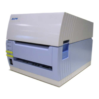
6.
Attach the latches of the Dispenser kit onto the holes
located below the two sides of
platen roller of the printer.
Close the
top cover, close the Pressure bracket and turn
the printer over again, with the
Main PCB is facing upward.
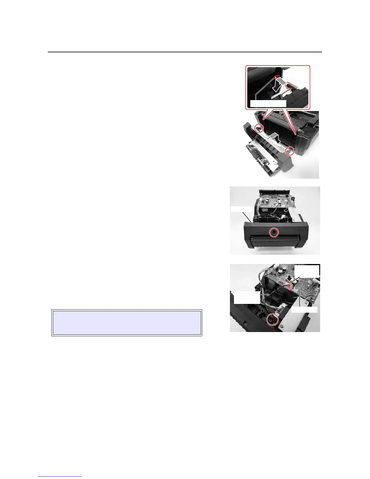
7. From the base of the Dispenser kit, secure the cutter unit
to the printer with the supplied
screw (circled) as shown.
8. Connect the Dispenser kit’s cable to the OPTION
connector on the MAIN PCB.
Route the
Dispenser kit’s cable through the groove (cir-
cled) of the printer as shown.
9. Assemble the Bottom Housing cover back to the printer
and secure with the three
screws removed in step 1.
CAUTION:
Ensure that no cables are pinched between parts when
you are assembling the cover.

 Loading...