121
www.sauservice.com
Sound volume adjustment is not ap-
propriate.
Board and Amplifier
malfunctioning
Sights are not aligned due to changes
in the surrounding environment.
LED board malfunctioning
Sensor unit malfunctioning
LED board and LED board cover are
contaminated.
Fuse on the connector board has
blown due to a momentary electrical
Overload.
Microswitch malfunctioning
LED board malfunctioning
Sensor board malfunctioning
Fuse on the connector board has
blown due to a momentary electrical
Overload.
Microswitch malfunctioning
Solenoid is broken.
Fuse on the connector board has
blown due to a momentary electrical
Overload.
The FL has burnt out.
Lamp has burnt out.
Using an unsupported card
Card reader settings are incorrect.
Connector is not connected properly.
IC card unit is dirty.
IC card unit is broken.
Foreign matter has entered the reader/
writer.
No sound is emit-
ted.
Control Unit sight-
ing is not satisfac-
tory.
During game play,
the control unit is
not operable for
shooting.
The operation
of the ACTION
button and SHOT
SELECTOR are
unsatisfactory.
The gun controller
does not vibrate.
The FL does not
light up.
The lamp does not
light up.
Cannot read prop-
erly from an IC
card or the IC card
is not detected.
Cannot insert an
IC card.
Adjust sound volume (see Sec. 9).
Perform the sound test and confirm (see
Sec. 9-2).
Perform sighting adjustment in the test
mode (see Sec. 9).
Check to ensure that the LED lights up. If it
does not light up, replace (see next page).
Replace the sensor unit (see Sec. 10).
Wipe off soiled surfaces (see Sec. 14 and
next page).
Fix the source of the overload, then replace
the fuse. <Fuse: 250V 200mA, 514-5086-
200> (see Sec. 16)
Check that the switches turn off and on us-
ing test mode. Replace the switch if it does
not operate (see Sec. 10).
Check to ensure that the LED lights up.
If does not light up, replace (see next page).
Replace the sensor board.
Fix the source of the overload, then replace
the fuse. <Fuse: 250V 200mA, 514-5086-
200> (see Sec. 16)
Check that the switches turn off and on us-
ing test mode.
Replace the switch if it does not operate
(see Sec. 10).
Replace the solenoid (see Sec. 10).
Fix the source of the overload, then replace
the fuse. <Fuse: 250V 200mA, 514-5086-
200> (see Sec. 16)
Replace the fluorescent light (see Sec. 14).
Replace the lamp (see Sec.14).
Correct the settings using Test mode
(see Sec. 9).
Check the operation using Test mode.
Check the connector connection.
Clean the IC card unit (see Sec. 11-1).
Contact your supplier
Clear out the foreigner matter (see Sec. 11-2).
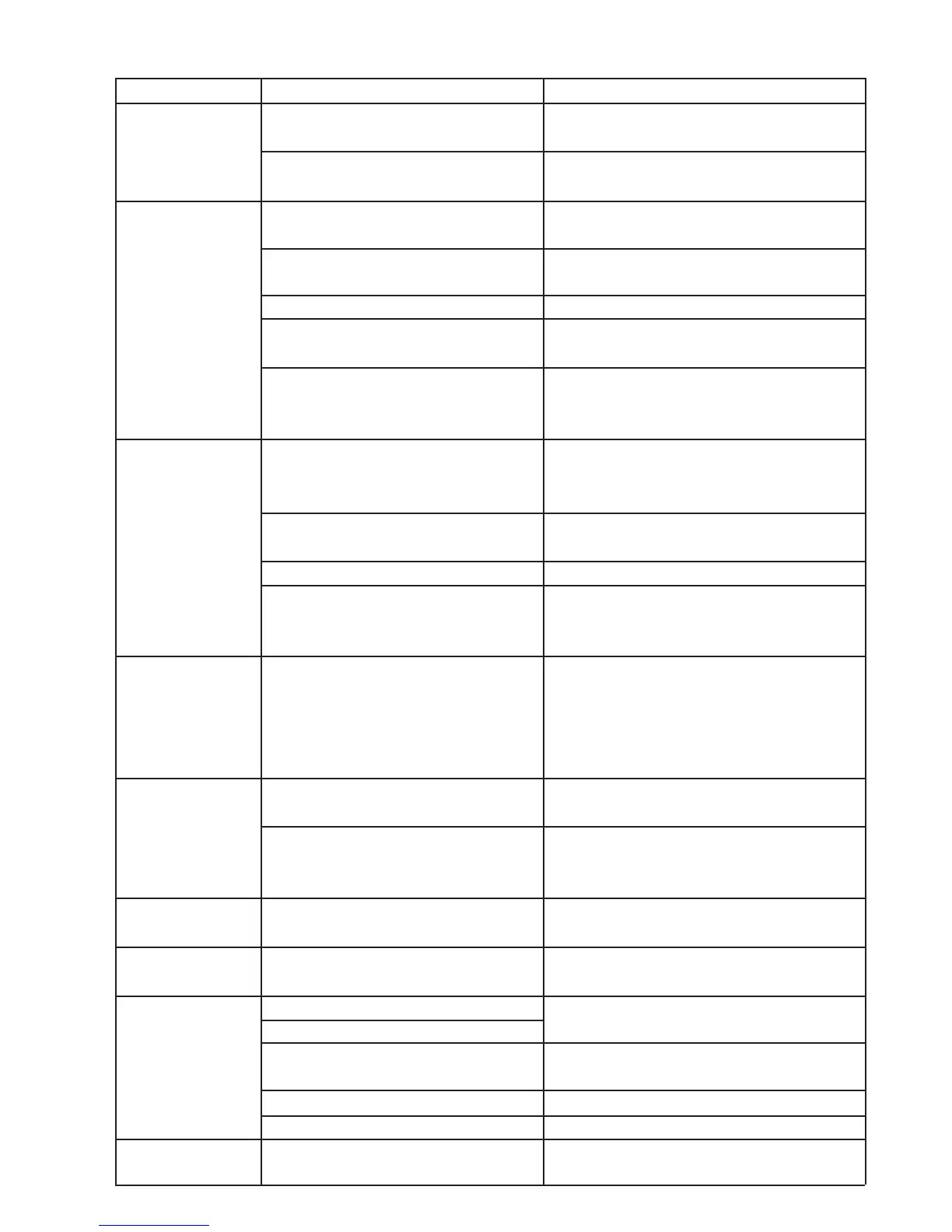
PROBLEMS CAUSE COUNTERMEASURES
TABLE 16.1b