Operating Instructions – Electronic Motor DRC.-..-SNI
35
4
Drive units with optional ASEPTIC / ASEPTICplus design
Mechanical Installation
Mounting positions DRC drive units in optional ASEPTIC / ASEPTIC
plus
design are delivered with pressure
compensation and breather valve installed according to the mounting position.
This is why DRC drive units in optional ASEPTIC / ASEPTIC
plus
design must only be
used in the mounting position specified in the order.
• Mounting position
–M1
–M2
–M3
–M4
–M5
–M6
• Cable entries
– Position 3 (not permitted for M4 mounting position)
– Position 2 (not permitted for M5 mounting position)
– Position X (not permitted for M6 mounting position)
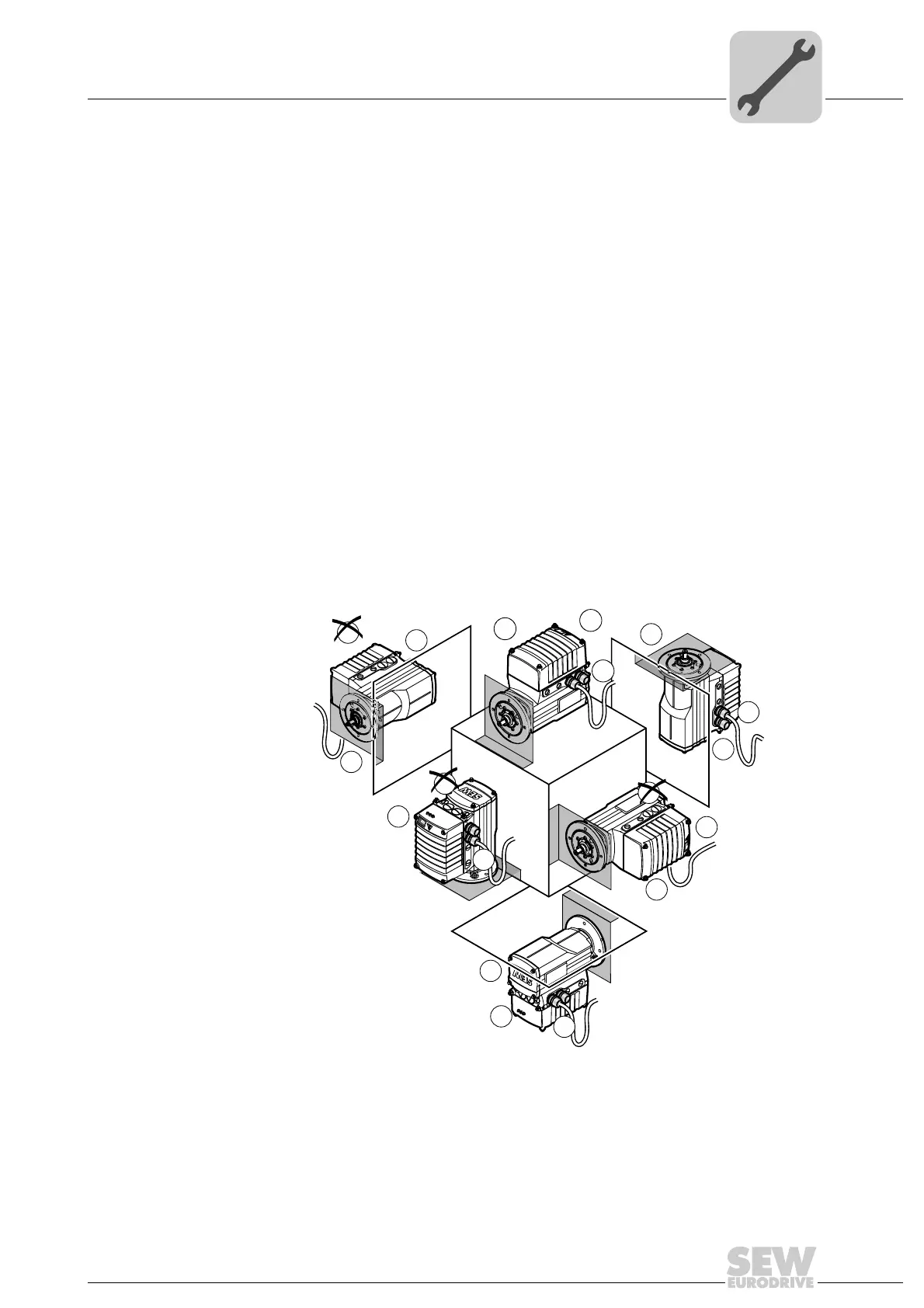
Mounting positions The following figure shows the position of the DRC drive unit when installed in mounting
positions M1 to M6:
4768583819
3
2
NET
RUN
DRIVE
M3
x
3
2
MOVIGEAR
®
B
SNI
NET
RUN
DRIVE
MOVIGEAR
®
B
SNI
M1
M2
M4
M5
M6
2
3
2
3
2
x
2
3
x
3
x
x
x