64
Operating Instructions – Electronic Motor DRC.-..-SNI
5
Assignment of optional plug connectors
Electrical Installation
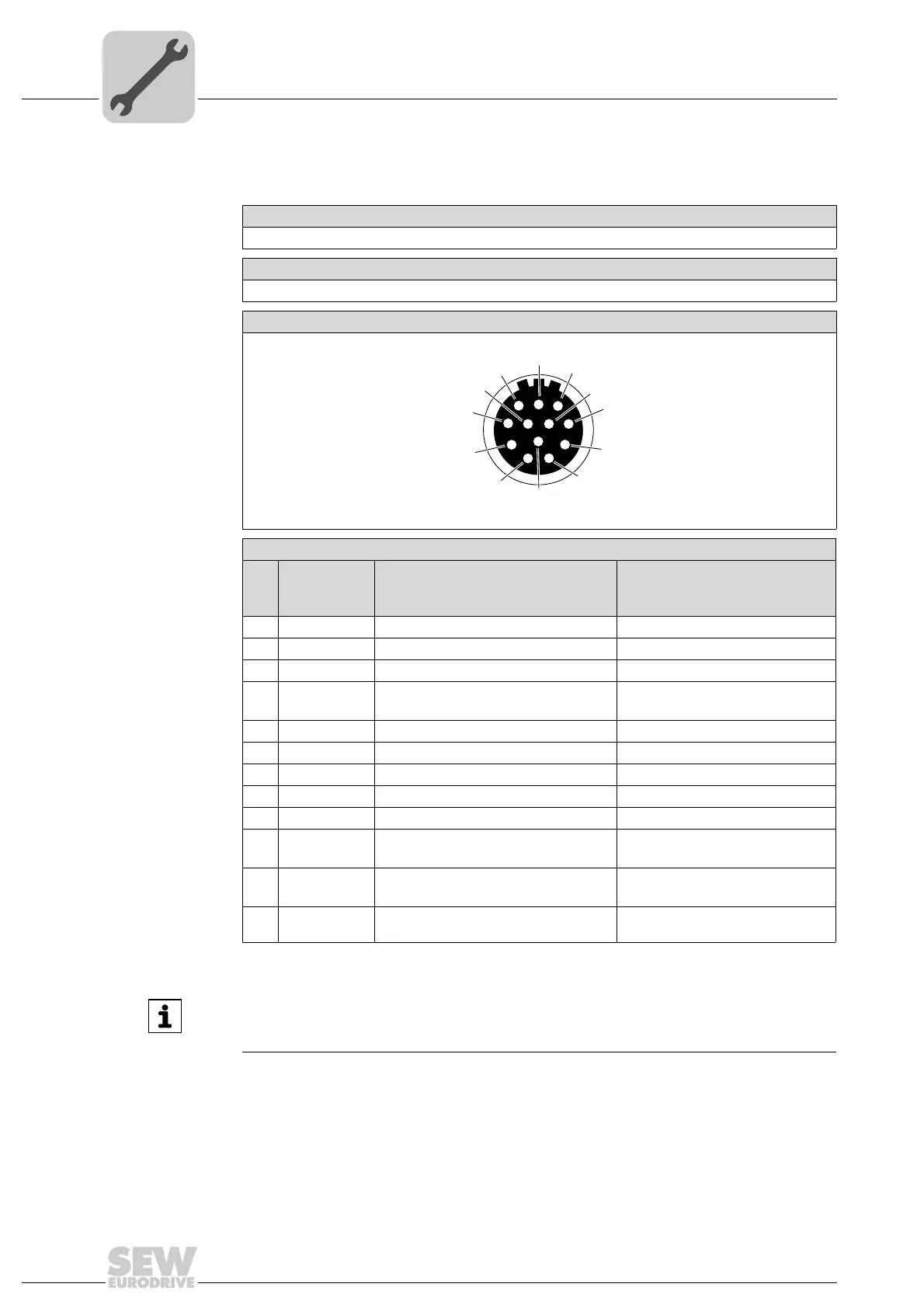
5.10.2 X5131: Digital inputs/outputs
The following table informs about this connection:
Function
Digital inputs/outputs for DRC MotionControl
Connection type
M23, P insert 12-pole, SpeedTec-capable, Intercontec, female, 0°-coded
Wiring diagram
2264820107
Assignment
No. Name Function
Motion control inputs
DIP switch S2/3 = OFF
Function
Local mode
DIP switch S2/3 = ON
1 DI01 DI01 sensor input CW/stop
2 DI02 DI02 sensor input CCW/stop
3 DI03 DI03 sensor input Setpoint f1/f2
4 DI04 DI04 sensor input Changeover
Automatic/local mode
5 n.c. Not connected Not connected
6 n.c. Not connected Not connected
7 n.c. Not connected Not connected
8 +24V_O Reserved DC 24 V output
9 0V24V_O Reserved 0V24 reference potential
10 0V24V_SEN 0V24 reference potential for sensors
1)
must be supplied via terminals
Reserved
11 +24V_SEN DC 24 V sensor supply
1)
Must be supplied via terminals X7.3
1) see operating instructions, chapter "Connecting DRC drive units"
Reserved
12 FE Equipotential bonding/functional ground Equipotential bonding/functional
ground
INFORMATION
Use actuator/sensor distributors with 4 slots for the sensor inputs. Use the DC 24 V
output only for local mode.