35
8027605/V1-0/2022-03| SICK S Y S T E M D E S C R I P T I O N | ALIS
Subject to change without notice
SYSTEM COMPONENTS 4
4.4 Cabinet incl. Controller
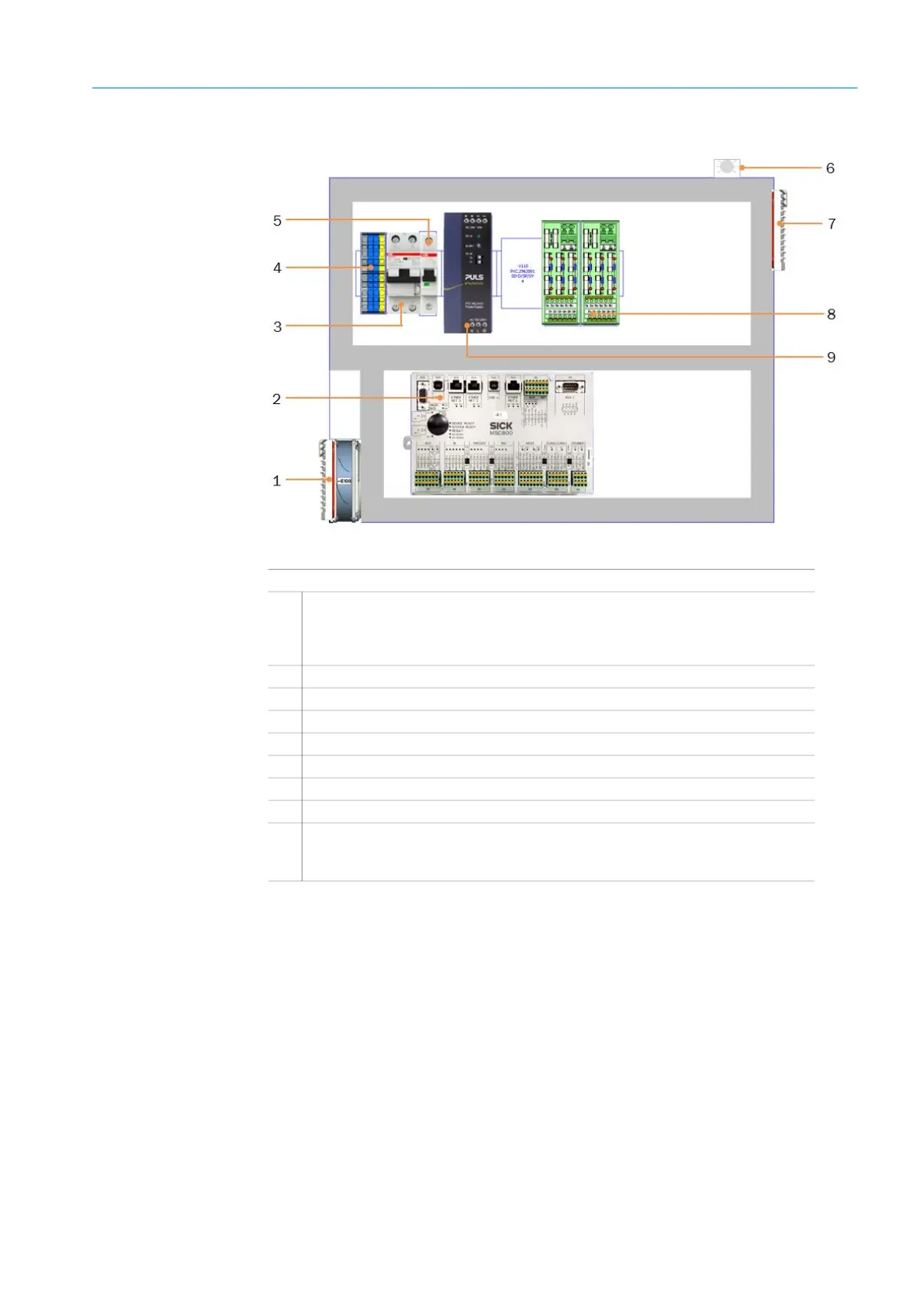
Fig. 17: Cabinet with system controller MSC800
Function
● The power supply unit supplies the voltage to the sensors in the track and trace system
● Contains the MSC800 system controller, the central control unit of the track and trace
system
● The MSC800 system controller coordinates all connected sensors, and assigns the
received read results to the respective bags
● The read results are output to the higher-level customer system in a host telegram with a
defined format
● The track and trace system is connected to the customer’s PROFINET IO network via the
CDF600 fieldbus module (option) (see below)
NOTE
A white status LED lights up as soon as voltage is applied to the cabinet.
Legend
1
Air inlet cooling (with filter mat and cooler)
– Used only in ALIS camera systems
– ALIS Laser and RFID systems are equipped with a smaller cabinet without
air inlet cooling
2
MSC800 system controller
3
FI/LS switch (RCBO)
4
Terminals for voltage supply IN (100-264 V AC/ 50-60 Hz)
5
Power supply circuit breaker
6
White status LED
7
Air outlet for cooling (with filter mat)
8
Terminals (24 V DC) and fuse module OUT
9
Power supply unit for supplying voltage to the system components
– 10A power supply for a ALIS Laser or RFID system
– 20A power supply for a ALIS camera System