45
8027605/V1-0/2022-03| SICK S Y S T E M D E S C R I P T I O N | ALIS
Subject to change without notice
ELECTRICAL INSTALLATION 6
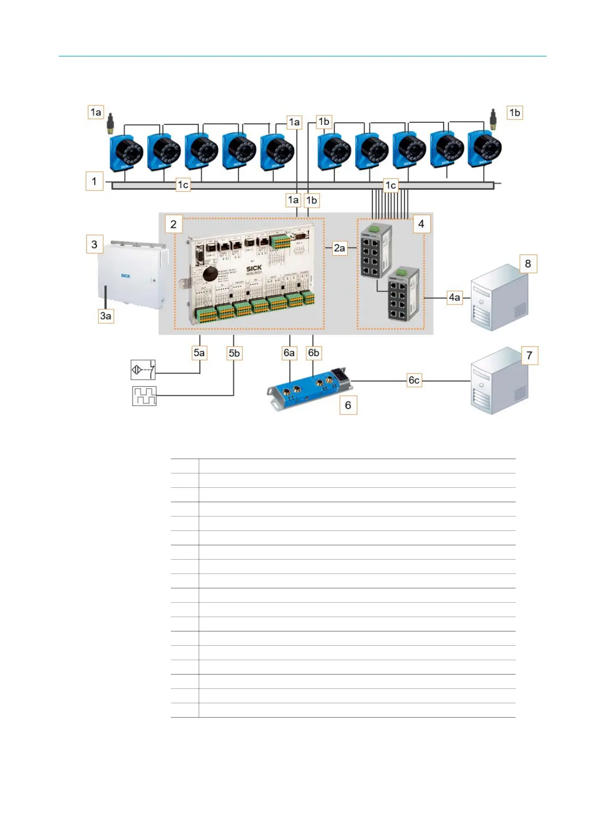
6.2 Connection Overview Lector654 - ALIS Camera
Fig. 24: Connection overview
1
Lector654
1a
CAN 1 (CAN bus, 24 V voltage supply, incremental signal, terminator)
1b
CAN 2 (CAN bus, 24 V voltage supply, incremental signal, terminator)
1c
Gbit Ethernet
2
MSC800 system controller
2a
Ethernet
3
Cabinet
3a
Feed 230 V / 50 Hz
4
Ethernet switches
4a
Gbit Ethernet (image output)
5a
Trigger signal
5b
Incremental signal
6
Field bus module (option)
6a
24 V voltage supply
6b
RS232 data cable (MSC800 system controller - field bus module
6c
Data output into PROFINET network
7
Customer's system
8
Image server (option)