70
8027605/V1-0/2022-03| SICKS Y S T E M D E S C R I P T I O N | ALIS
Subject to change without notice
9 MAINTENANCE AND REPAIR
Replacing the power supply unit
▸ Interrupt the supply voltage to the cabinet.
Disconnect and remove the cables from the power supply module.
▸ Remove the defective power supply module from the cabinet. To do this, use a suitable
screwdriver to slide the black clip on the rear wall backwards.
▸ Lift the power supply unit and pull it forward and out of the bracket.
Installing the power supply unit
▸ Place the new power supply module on the mounting rail of the cabinet and press back-
wards until the power supply module audibly engages.
▸ Reconnect all cables to the power supply unit.
▸ Restore the supply voltage to the cabinet.
Setting the output voltage
The power supply modules are factory preset with a 24 V output voltage.
▸ Set the output voltage on the power supply module using the potentiometer.
▸ Check that the output voltage is correct.
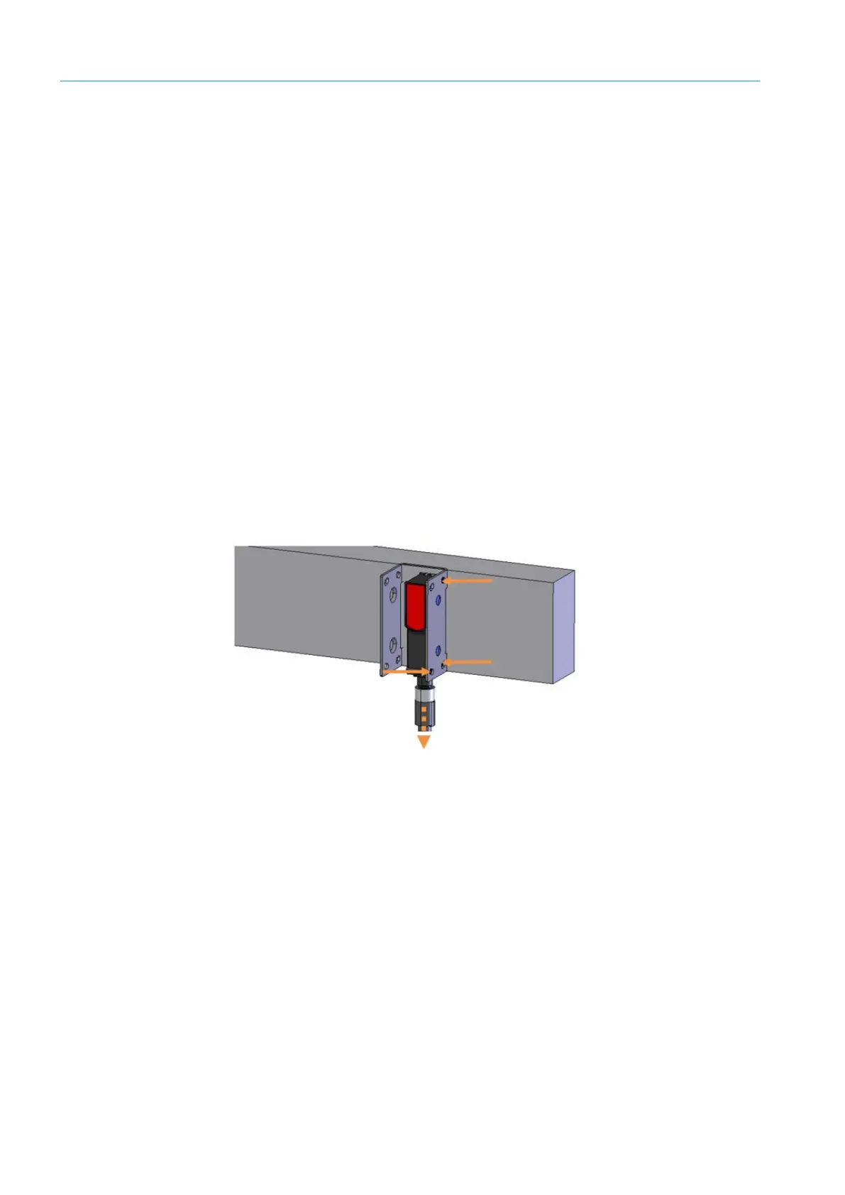
9.4.7 Photoelectric Retro-Refelctive Sensor Replacing
A defective retro-reflective sensor must be replaced immediately.
Fig. 57: Replacing the photoelectric retro-reflective sensor
▸ Unscrew the M12 plug connector from the male connector on the photoelectric retro-
reflective sensor.
▸ Loosen fixing screws.
Note Hold the photoelectric retro-reflective sensor firmly with one hand during the proce-
dure.
▸ Remove the defective photoelectric sensor from the mounting bracket.
▸ Screw the replacement device onto the mounting bracket.
▸ Screw the M12 plug connector onto the male connector on the photoelectric retro-reflec-
tive sensor.
▸ Align the photoelectric sensor correctly on the reflector. The reflector must be in line with
the beam path of the photoelectric retro-reflective sensor.
▸ Check that the photoelectric retro-reflective sensor is operating correctly.