62
8027605/V1-0/2022-03| SICKS Y S T E M D E S C R I P T I O N | ALIS
Subject to change without notice
9 MAINTENANCE AND REPAIR
Replacing the components via quick release
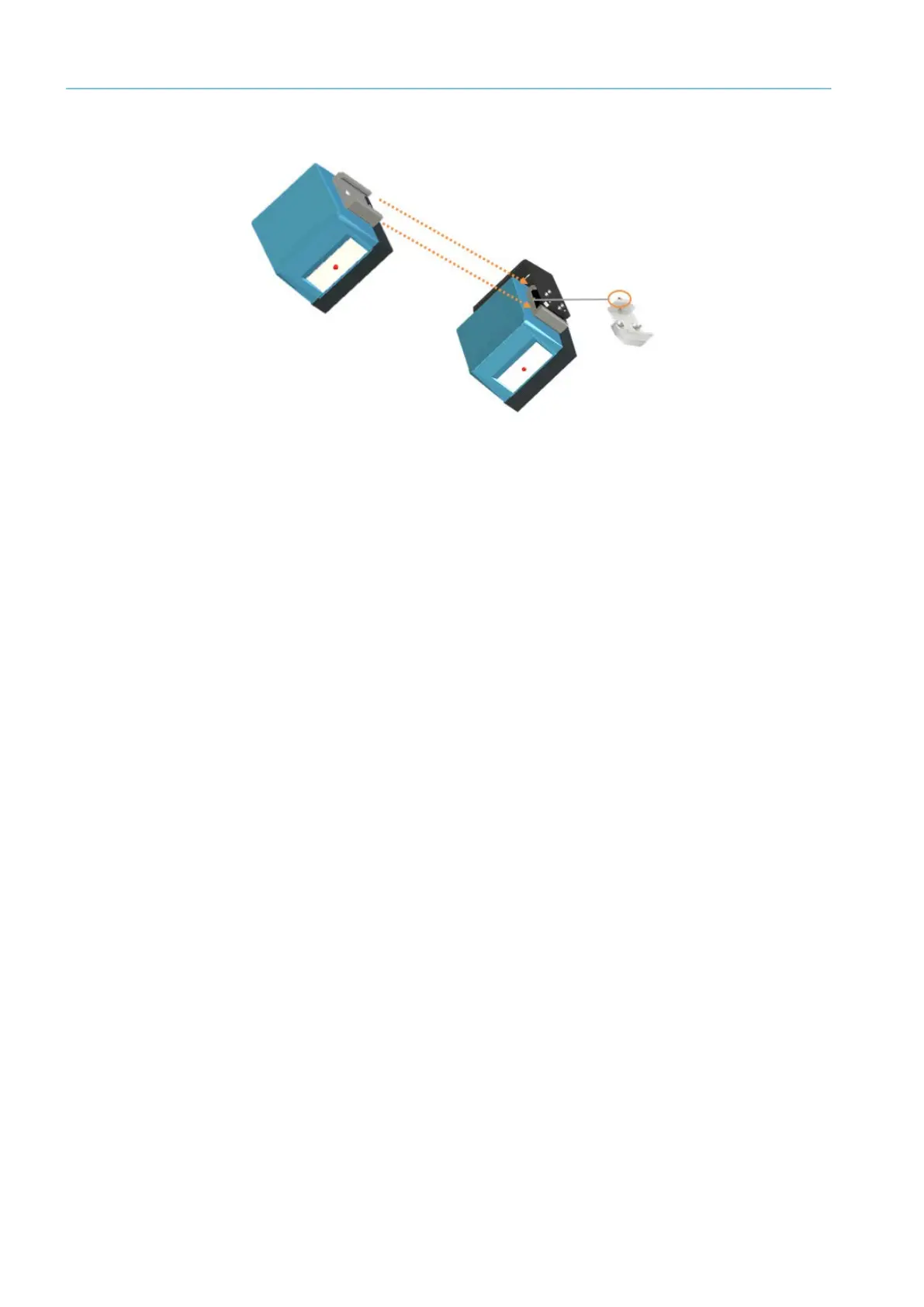
Fig. 44: Clamping profile
▸ Remove the M8 setscrew used to fasten the clamp to the clamping profile.
▸ Remove the clamping profile, with the CLV691 mounted on it, from the clamp.
▸ Remove the M6 countersunk screws and detach the CLV691 from the clamping profile.
The mounting bracket remains fastened to the main frame together with the clamp.
▸ Fit the clamping profile to the replacement device then fasten the device in place with
the two M6 countersunk screws.
▸ Insert the clamp, with the replacement device mounted on it, into the clamping profile.
▸ Fasten the clamp to the clamping profile with the M8 setscrew.
The component is replaced.
Completing the work
▸ Screw the cloning connector back again.
▸ Switch on the track and trace system. When the voltage supply is connected, the config-
uration stored in the parameter memory of the cloning connector is transferred to the
fixed mount bar code scanner.
▸ Check that the Ready LED is lit up green.
The replacement is complete.
Note
To correctly mount the connector on the side of the device, note the guide holes on the
fixed mount bar code scanner and the notch at the top-left corner of the cloning connec-
tor.