Operating instructions Chapter 11
Flexi Classic
8011509/YPP0/2015-10-26 © SICK AG • Industrial Safety Systems • Germany • All rights reserved 101
Subject to change without notice
Technical specifications
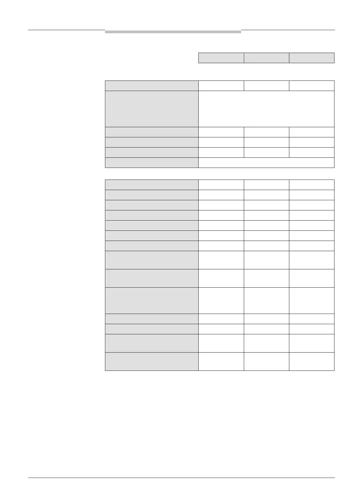
11.1.2 UE410-GU module
Minimum Typical Maximum
Supply circuit (A1, A2)
Supply voltage U
B
19.2 V DC 24 V DC 30 V DC
Type of supply voltage PELV or SELV
The current from the power supply that supplies the
main module must be limited externally to max. 6 A
— either by the power supply itself or by a fuse.
Residual ripple U
ss
– – 3 V
Power consumption – – 3 W
Maximum switch-on time – – 60 s
Short-circuit protection 4 A gG with tripping characteristic B or C
Input circuit (I1-I4, I
P
, I5, I6, I
N
)
Number of inputs – – 8
Input voltage (high) 13 V DC – 30 V DC
Input voltage (low) –5 V DC – 5 V DC
Input current (high) 2.4 mA 3 mA 3.8 mA
Input current (low) –2.5 mA – 2.1 mA
Input capacitance 9 nF 10 nF 11 nF
Minimum switch-off time
20)
(I1/I2) 20 ms – –
Minimum switch-off time
20)
(I3/I4)
program 6, 7
7 ms – –
Minimum switch-off time
20)
(I3/I4)
program 2, 3, 4, 5, 8, 9
20 ms – –
Maximum interruption time for the
input signal without switching the
output (Q1)
– – 1 ms
Local power-up delay (I1-I4) – – 70 ms
Local reset time – – 124 ms
Teach-in time of ENTER button
(during power-up)
– – 3 s
Duration of actuation of the reset
button (I6)
50 ms – 5 s
20)
Time without sensor, in addition the data for the sensors connected apply.
UE410-GU

 Loading...


