Chapter 3 Operating instructions
Flexi Classic
28 © SICK AG • Industrial Safety Systems • Germany • All rights reserved 8011509/YPP0/2015-10-26
Subject to change without notice
Product description
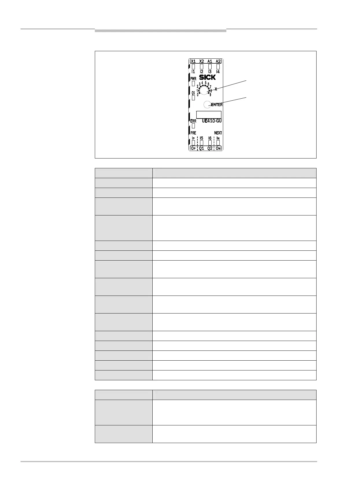
3.4.1 Controls and status indicators
LED indicators Meaning
PWR (green) Supply voltage is present.
Q1 (green) Safety output Q1 is high.
ERR (red flashing)
Indication for erroneous operational status on this module, see
chapter 10 “Diagnostics” on page 93
ERR (red)
Indication for erroneous operational status on the whole system
(the error is on another module), see chapter 10 “Diagnostics”
on page 93
I1/I2 (green) Global cut-off path closed
I3/I4 (green) Cut-off path closed
I1/I2 (green flashing
in phase)
Cross-circuit between I1/I2
I3/I4 (green flashing
in phase)
Cross-circuit between I3/I4
I1/I2 (green flashing
out of phase)
Process error at I1/I2
I3/I4 (green flashing
out of phase)
Process error at I3/I4
I5 (green) External device monitoring contact is closed.
I6 (green) Reset button is closed.
I
P
(green) Input I
P
is high.
I
N
(green) Input I
N
is high.
Other indicators Device error, see chapter 10 “Diagnostics” on page 93
Switch/button Function
X
10-step rotary switch (position 0 forbidden) for setting an input
circuit function, see section 3.7 “UE410-GU programs” on
page 49
ENTER
Button for accepting the system configuration (Teach-in), see
section 9.1 “Accepting the system configuration” on page 92
and status indicators
indications
operating elements
system configuration

 Loading...


