Operating instructions Chapter 3
Flexi Classic
8011509/YPP0/2015-10-26 © SICK AG • Industrial Safety Systems • Germany • All rights reserved 39
Subject to change without notice
Product description
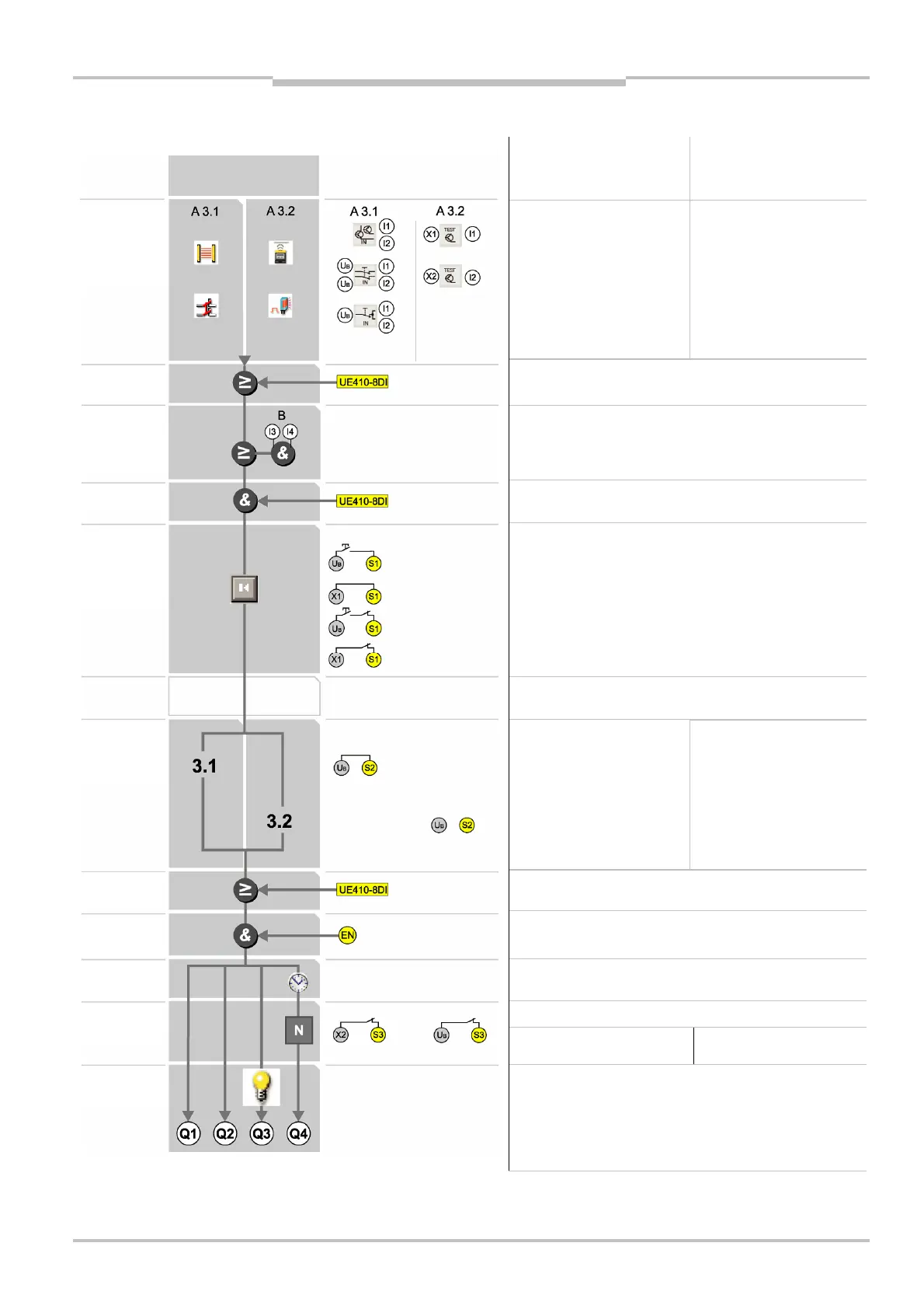
3.6.3 Programs 3.1 and 3.2
Program 3.1 Program 3.2
Single-channel N/C contact
Dual-channel equivalent N/C
contact (not cross-circuit
detecting)
ESPE (sensors with
semiconductor output)
X1-I1 IN4000; Bridge X2-I2.
X2-I2 ESPE (sensors with PNP
semiconductor output)
Bridge X1-I1.
Bridge the input circuit not
used (does not apply to I3-I4).
OR with UE410-8DI — switch position 7
Muting sensors I3-I4 (PNP switching)
AND with UE410-8DI — switch position 1-6
Connecting of S1:
∂ with restart interlock Q1/Q2, without EDM
∂ without restart interlock Q1/Q2, without EDM
∂ with restart interlock Q1/Q2, with EDM
∂ without restart interlock Q1/Q2, with EDM
Connecting of S2:
S2 is connected to U
B
.
Connecting of S2:
S2 may not be connected.
OR limited 60 s with UE410-8DI — switch position 8
Always wire ENABLE (expected 24 V DC)!
At ENABLE low Q1-Q4 are always low.
Off delay acts only on Q4
(not on UE410-xxxT0).
Connecting of S3:
with/without EDM Q4
∂ retriggering ON
with/without EDM Q4
∂ retriggering OFF
Undelayed OSSDs Q1/Q2
Delayable OSSD Q4
Output for muting lamp and Reset required lamp Q3
Q3 permanently High: Muting active
Q3 1 Hz flashing: Reset required
sensors
interlock
Bypass
ENABLE
Retriggering
1 logic path

 Loading...


