Chapter 4 Operating instructions
Flexi Classic
72 © SICK AG • Industrial Safety Systems • Germany • All rights reserved 8011509/YPP0/2015-10-26
Subject to change without notice
Special applications and
functions
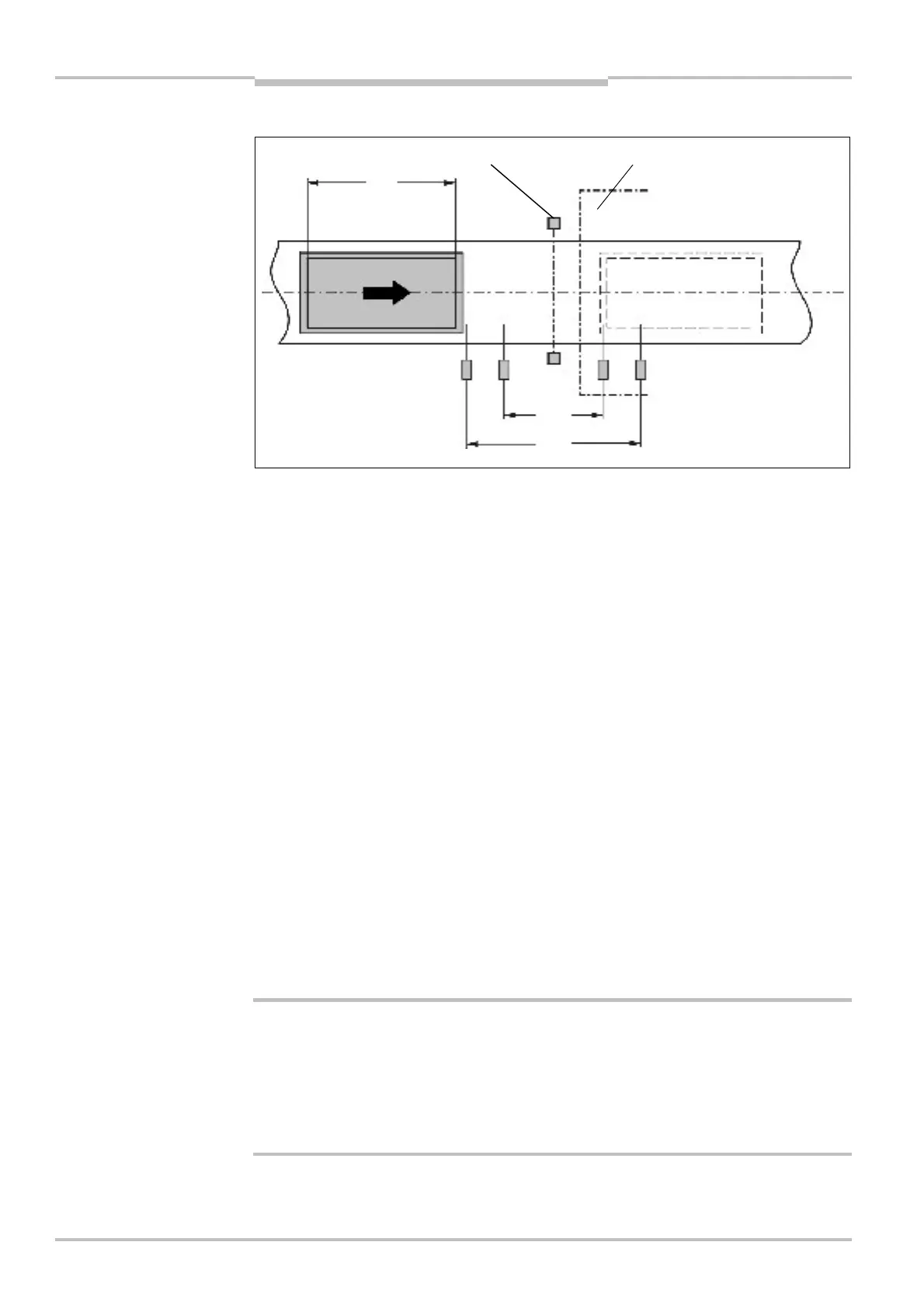
4.7.2 4-sensor muting, sequential layout
In the example, the material moves from left to right. As soon as the muting sensors A1 &
A2 are activated, the protection provided by the protective device (ESPE) is muted. The
protection remains muted until one of the sensors in the muting sensor pair B1 & B2 is
clear again.
4.7.3 Muting with UE410-MU/UE410-XU
A simple muting function can be implemented at the UE410-MU/UE410-XU modules
(programs 3.1 and 3.2) by using inputs I3 and I4 for the muting sensors. Inputs I3 and I4
are AND-linked to each other and mute the safety sensor equipment connected to I1/I2.
A muting lamp can be connected to output Q3.
Features of the muting function for UE410-MU/UE410-XU:
• The outputs on the muting sensors must be “0” on powering up the Flexi Classic, other-
wise a process error will be generated and the system will generate ERROR.
• Muting duration indefinite
• Switching behaviour of the muting sensors is not limited in time.
• Direction independent muting
• Inputs I3/I4 for muting sensors can be “1” simultaneously.
• The muting lamp is not current monitored and has two functions:
– Muting lamp ON continuously, then muting is active,
– Muting lamp flashes at 1 Hz, then the Reset required is active.
Muting with 4 sensors:
• With this 4-sensor muting two muting sensors each are connected to one input of the
UE410-MU/UE410-XU. Take into account that the muting sensors A1/B2 and A2/B1
are combined respectively.
• Only “high-side”-switching sensors may be used for 4-sensor muting. Thereby it has to
be ensured that a “high” always overwrites a “low”. This type of muting may only be
used after thorough risk analysis/error analysis.
muting
WARNING
2
1
3

 Loading...


