Operating instructions Chapter 3
Flexi Classic
8011509/YPP0/2015-10-26 © SICK AG • Industrial Safety Systems • Germany • All rights reserved 59
Subject to change without notice
Product description
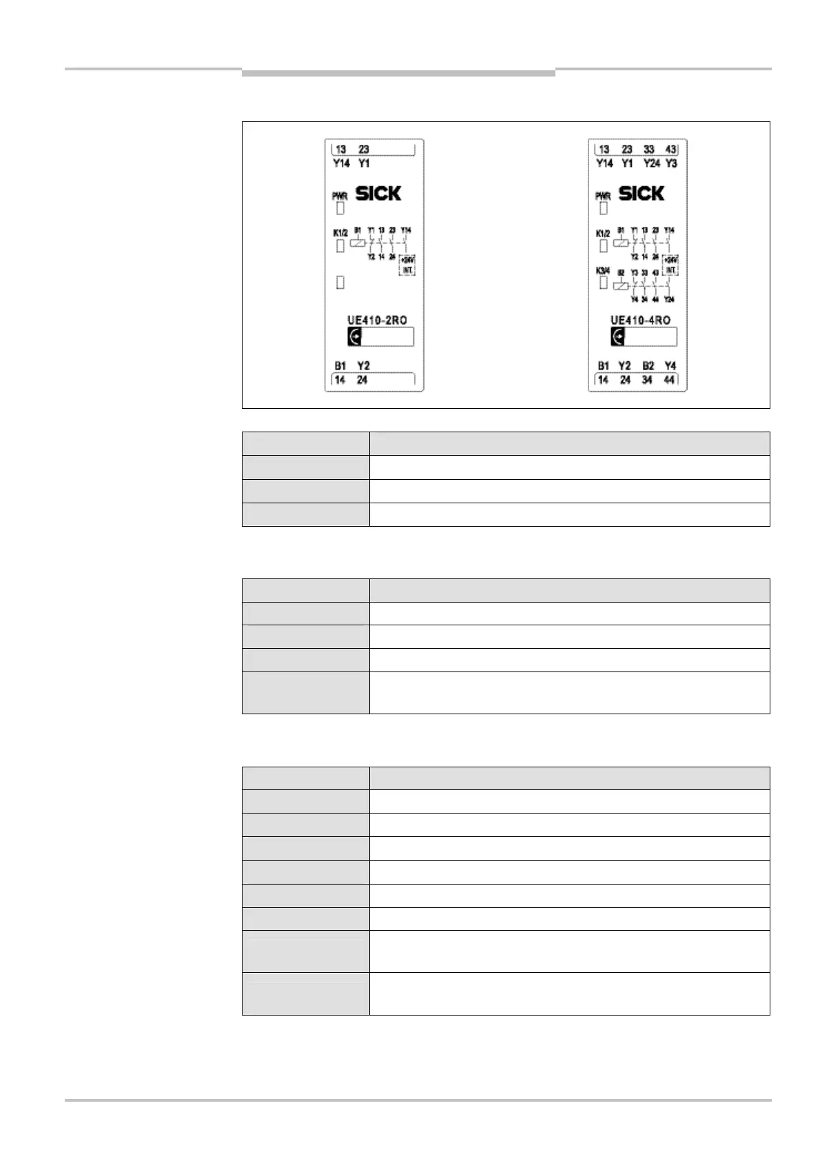
3.9.3 Controls and status indicators
LED indicators Meaning
PWR (green) Supply voltage via safety bus is present
K1/2 (green) Relay K1/K2 — safety contacts closed
K3/4 (green) Relay K3/K4 — safety contacts closed
3.9.4 UE410-2RO inputs and outputs
Assignment Description
B1 Connecting relay K1/K2
13/14 and 23/24 Safety contacts for switch-off circuit K1/K2
Y1/Y2 Feedback circuit external device monitoring (EDM), N/C contact
Y14
N/O safety contact K1/K2, current-limited,
see chapter 11 “Technical specifications” on page 96
3.9.5 UE410-4RO inputs and outputs
Assignment Description
B1 Connecting relay K1/K2
B2 Connecting relay K3/K4
13/14 and 23/24 Safety contacts for switch-off circuit outputs K1/K2
33/34 and 43/44 Safety contacts for switch-off circuit outputs K3/K4
Y1/Y2 Feedback EDM K1/K2, N/C contact
Y3/Y4 Feedback EDM K3/K4, N/C contact
Y14
N/O safety contact K1/K2, current-limited,
see chapter 11 “Technical specifications” on page 96
Y24
N/O safety contact K3/K4, current-limited,
see chapter 11 “Technical specifications” on page 96
UE410-2RO/UE410-4RO
controls and status indicators
UE410-2RO/UE410-4RO
indicators
UE410-2RO
UE410-4RO

 Loading...


