Operating instructions Chapter 11
Flexi Classic
8011509/YPP0/2015-10-26 © SICK AG • Industrial Safety Systems • Germany • All rights reserved 105
Subject to change without notice
Technical specifications
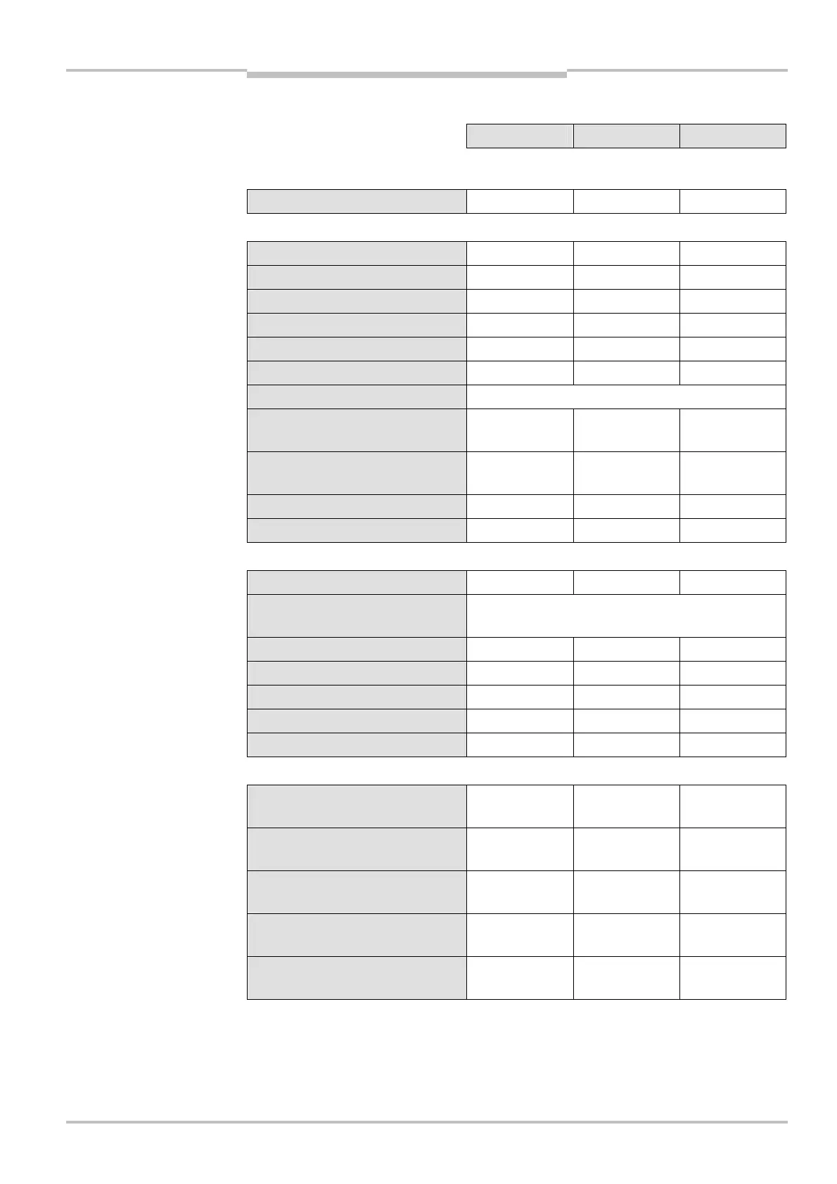
11.1.3 UE410-8DI input extension module
Minimum Typical Maximum
Supply circuits (via UE410-MU or UE410-GU)
Power consumption – – 3 W
Input circuit (I1-I8)
Number of inputs – – 8
Input voltage (high) 13 V DC – 30 V DC
Input voltage (low) –5 V DC – 5 V DC
Input current (high) 2.4 mA 3 mA 3.8 mA
Input current (low) –2.5 mA – 2.1 mA
Input capacitance 9 nF 10 nF 11 nF
Minimum switch-off time See response times
Break time of the input signal
without switching of the outputs
– – 1 ms
Monitoring of synchronisation,
switch position 3, 5
– 1500 ms –
Power-up delay 70 ms – –
Reset time – – 120 ms
Output circuit (X1-X8)
Number of outputs – – 8
Type of output
PNP semiconductors, short-circuit protected, cross-
circuit detecting
27)
Output voltage 16 V DC – 30 V DC
Output current
28)
– – 30 mA
Test period – – 40 ms
Load capacity – – 1,000 nF
Cable resistance – – 100 Ω
Response time UE410-8DI on safety outputs UE410-MU/UE410-XU (Q1-Q4)
Response time
switch setting 6, 7
29)
– – 17 ms
Response time
switch setting 1, 2, 3, 4, 5, 8
29)
– – 34 ms
Response time switch setting 2
pressure sensitive mat
29)
– – 42 ms
Response time of all programs
with tested ESPE Cat. 4 (e.g. L41)
– – 60 ms
Response time
30)
on connection of
Flexi Loop
60 ms
27)
Cross circuit detecting only within a module.
28)
The total output current for a Flexi Classic system is limited. The current for supplying all sensors that are
connected to the UE410-MU/XU (X1/X2) and UE410-8DI (X1-X8) must be I < 600 mA and the current on a
Flexi Classic gateway must be I<100 mA. If this total current is insufficient, please contact the SICK hotline.
29)
Time without sensor, the data for the sensors connected apply in addition.
UE410-8DI

 Loading...


