Chapter 3 Operating instructions
Flexi Classic
54 © SICK AG • Industrial Safety Systems • Germany • All rights reserved 8011509/YPP0/2015-10-26
Subject to change without notice
Product description
3.8.4 Reciprocal assignment — Mirror mode
Switch position 9:
The functionality and logical link of input B is assigned to the logic of input A. Input group A
then has 8 inputs.
Or:
The functionality and logical link of input A is assigned to the logic of input B. Input group B
then has 8 inputs.
Function 9 may only be selected for one of the two input groups respectively. Otherwise a
device error ERROR is generated and the ERR LED flashes.
3.8.5 Connection of sensors to the UE410-8DI
A UE410-8DI has two test pulse generators. This means that short-circuits between odd
(X1) and evenly (X2) numbered outputs will be detected. Short-circuits between two odd
(i.e. X1 and X3) or two evenly (i.e. X2 and X4) numbered outputs will not be detected.
Please heed this when wiring the safety sensors.
• The assignment of outputs X1 to X8 to inputs I1 to I8 depends on the selected rotary
switch position.
• The functions of logic paths A and B can be set independently of each other.
When AND logic is used, unused inputs have to be jumpered in accordance with the state
logical “1” (e.g. X4-I4, U
B
-I4)!
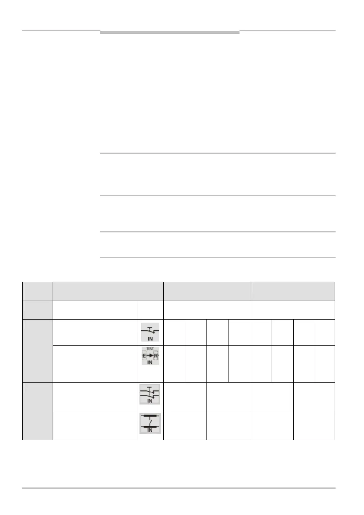
= Connect the sensors (type depending on the switch position) in accordance with
Tab. 24.
Switch
position
Input A Input B
0
All the inputs of Group A or B
are not used
N.c. Terminals not connected Terminals not connected
AND
4 × single-channel with testing
X1-I1 X2-I2 X3-I3 X4-I4 X5-I5 X6-I6 X7-I7 X8-I81
AND
4 × single-channel with
sensors that can be tested
(ESPE)
X1-I1 X2-I2 X3-I3 X4-I4 X5-I5 X6-I6 X7-I7 X8-I8
AND
2 × dual-channel, cross-circuit
detection
X1-I1
X2-I2
X3-I3
X4-I4
X5-I5
X6-I6
X7-I7
X8-I8
2
AND
2 × dual-channel, cross-circuit
detection
X1-I1
X2-I2
X3-I3
X4-I4
X5-I5
X6-I6
X7-I7
X8-I8
Note
WARNING
Notes
WARNING

 Loading...


