Operating instructions Chapter 3
Flexi Classic
8011509/YPP0/2015-10-26 © SICK AG • Industrial Safety Systems • Germany • All rights reserved 51
Subject to change without notice
Product description
3.8 UE410-8DI input extension module
The UE410-8DI module is an input extension with 8 safe inputs.
A UE410-8DI is used to add additional inputs either to a UE410-MU, UE410-GU or UE410-
XU. The simultaneous use of up to UE410-8DI per UE410-MU, UE410-GU or UE410-XU is
possible.
A UE410-8DI input extension module acts exclusively on the next UE410-MU, UE410-GU or
UE410-XU module on the left in the module structure. It has two separate input groups
each with 4 inputs for connecting safe signal detectors and sensors. The UE410-8DI has a
separate switch for each input group (input A and B). The 9 positions on the rotary switch
determine the type of safety component which can be connected and with which logic (OR,
AND or Bypass) it will act on the UE410-MU, UE410-GU or UE410-XU.
The input group A of a UE410-8DI acts on the logic path A of a connected UE410-MU,
UE410-GU or UE410-XU.
The input group B of a UE410-8DI acts on the logic path B of a connected UE410-MU,
UE410-GU or UE410-XU.
Each input group consists of two input pairs. At input A, for example, this is I1/I2 and
I3/I4. Two inputs are AND-linked and form an input pair. This does not apply for switch
position 1.
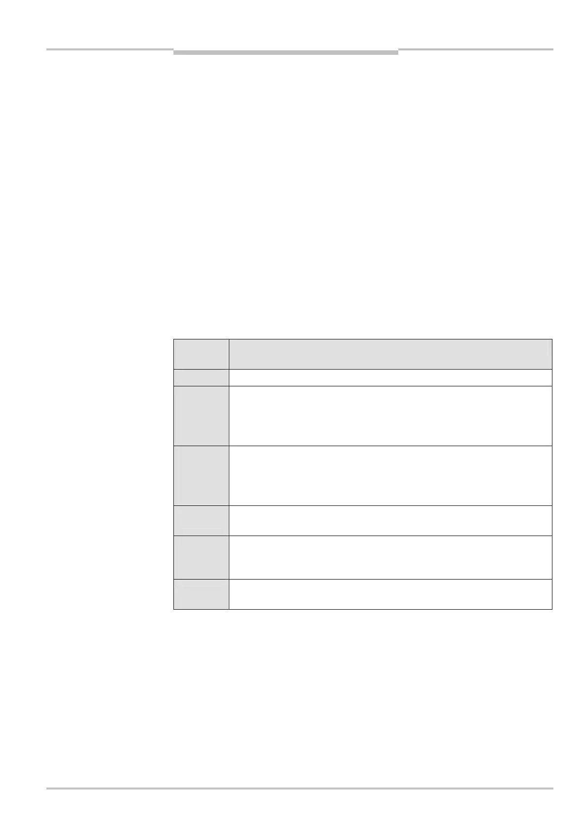
Switch
position
Description
0 Selected input (A/B) is inactive — input signals are ignored.
1
The connected single-channel sensor equipment is AND-linked to the
respective logic path of the UE410-MU/UE410-GU/UE410-XU modules.
Unused inputs have to be jumpered in accordance with the state logical “1”
(e.g. X4-I4, U
B
-I4).
2-6
The connected dual-channel sensor equipment is AND-linked to the
respective logic path of the UE410-MU/UE410-GU/UE410-XU modules.
Unused inputs have to be jumpered in accordance with the state logical “1”
(e.g. X4-I4, U
B
-I4).
7
The connected dual-channel sensor equipment is OR-linked to the
respective logic path of the UE410-MU/UE410-GU/UE410-XU modules.
8)
8
The connected dual-channel sensor equipment is Bypass-linked to the
respective safety outputs of the UE410-MU/UE410-GU/UE410-XU modules
(time-limited OR function).
9)
9
Reciprocal assignment of input A/input B in order to link all 8 inputs on a
logic path.
For more informationen on this topic see section 4.12 “Grouping of subsystems” on
page 78.
8)
An OR function that acts on the global cut-off path on the UE410-GU (switch position 7, input A on the
UE410-8DI) is not permitted and will result in a configuration error (ERROR).
9)
A bypass function that acts on the global cut-off path on the UE410-GU (switch position 8, input A on the
UE410-8DI) is not permitted and will result in a configuration error (ERROR).
positions

 Loading...


