Chapter 3 Operating instructions
Flexi Classic
24 © SICK AG • Industrial Safety Systems • Germany • All rights reserved 8011509/YPP0/2015-10-26
Subject to change without notice
Product description
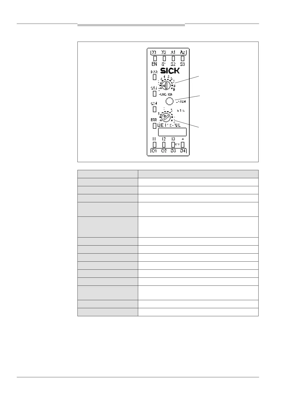
3.3.1 Controls and status indicators
LED indicators Meaning
PWR (green) Supply voltage present
Q1/Q2, Q3/Q4 (green) Switching state of the safety outputs (high level)
Q3/Q4 (green flashing) Q3/Q4 to high level during the course of the delay time
ERR (red flashing)
Indication for erroneous operational status on this
module, see chapter 10 “Diagnostics” on page 93
ERR (red)
Indication for erroneous operational status on the whole
system (the error is on another module), see chapter 10
“Diagnostics” on page 93
EN, S1-S3 (green) Voltage is present.
I1-I4 (green) Signal is present.
I1/I2 flash in phase Cross-circuit between I1/I2
I3/I4 flash in phase Cross-circuit between I3/I4
I1/I2 flash out of phase Process error at I1/I2
I3/I4 flash out of phase Process error at I3/I4
I1 to I4 flashes
Synchronization time/concurrence error, expected signal
is not present at the respective input.
S1-S3 flashes Expected signal is not present (e.g. EDM or Reset).
Other indicators Device error, see chapter 10 “Diagnostics” on page 93
and status indicators
indications
system configuration
(not on UE410-xxxT0),
see Tab. 10

 Loading...


