Chapter 3 Operating instructions
Flexi Classic
46 © SICK AG • Industrial Safety Systems • Germany • All rights reserved 8011509/YPP0/2015-10-26
Subject to change without notice
Product description
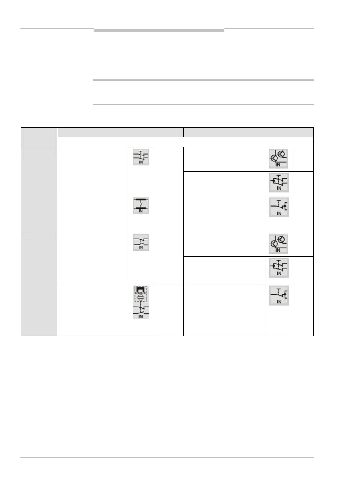
3.6.10 Connection of sensors to the UE410-MU/UE410-XU
• The allocation of the outputs X1 to X2 to the inputs I1 to I4 depends on the selected
input circuit function.
• The functions of logic paths A and B can be set independently of each other.
Warning!
Unused inputs must be bridged as per the state shown!
= Connect the sensors (type depending on the switch position) in accordance with
Tab. 18.
Program Inputs of logic path A Inputs of logic path B
0 Module inactive
Dual-channel non-isolated
semiconductors
U
B
-I3
U
B
-I4
Dual-channel equivalent
N/C contact
cross-circuit detecting
synchronisation time
monitoring 1500 ms
X1-I1
X2-I2
Dual-channel N/C contact,
three-wire
U
B
-I3
U
B
-I4
1
Four-wire
cross-circuit detecting
(e.g. cross-circuit detecting
switching mats)
X1-I1
X2-I2
Single-channel N/C contact U
B
-I3
U
B
-I4
Dual-channel non-isolated
semiconductors
U
B
-I3
U
B
-I4
Dual-channel
complementary N/C
contact
cross-circuit detecting
synchronisation time
monitoring 1500 ms
X1-I1
X2-I2
Dual-channel N/C contact,
three-wire
U
B
-I3
U
B
-I4
2
Dual-channel
complementary N/C
contact
cross-circuit detecting
synchronisation time
monitoring 1500 ms
X1-I1
X2-I2
Single-channel N/C contact U
B
-I3
U
B
-I4
Notes
WARNING

 Loading...


