Chapter 5 Operating instructions
Flexi Classic
80 © SICK AG • Industrial Safety Systems • Germany • All rights reserved 8011509/YPP0/2015-10-26
Subject to change without notice
Mounting/dismantling
5 Mounting/dismantling
This chapter describes the mounting of the modules and the anti-manipulation cover for
the Flexi Classic modular safety controller.
The following steps are necessary after mounting and installation:
• completing the electrical connections (chapter 6)
• configuration (chapter 9)
• checking the installation (section 8.2)
5.1 Steps for mounting the modules
The Flexi Classic system is only for use in a control cabinet rated to at least IP 54.
• In a Flexi Classic system the main module UE410-MU is positioned at the extreme left
and one of the optional gateways, e.g. UE410-PRO, at the extreme right.
• The connection between the modules is effected by means of the plug connection
integrated in the housing.
• Mounting according to EN 50 274
• The modules are located in a 22.5 mm wide housing for 35 mm DIN mounting rails as
per EN 60 715.
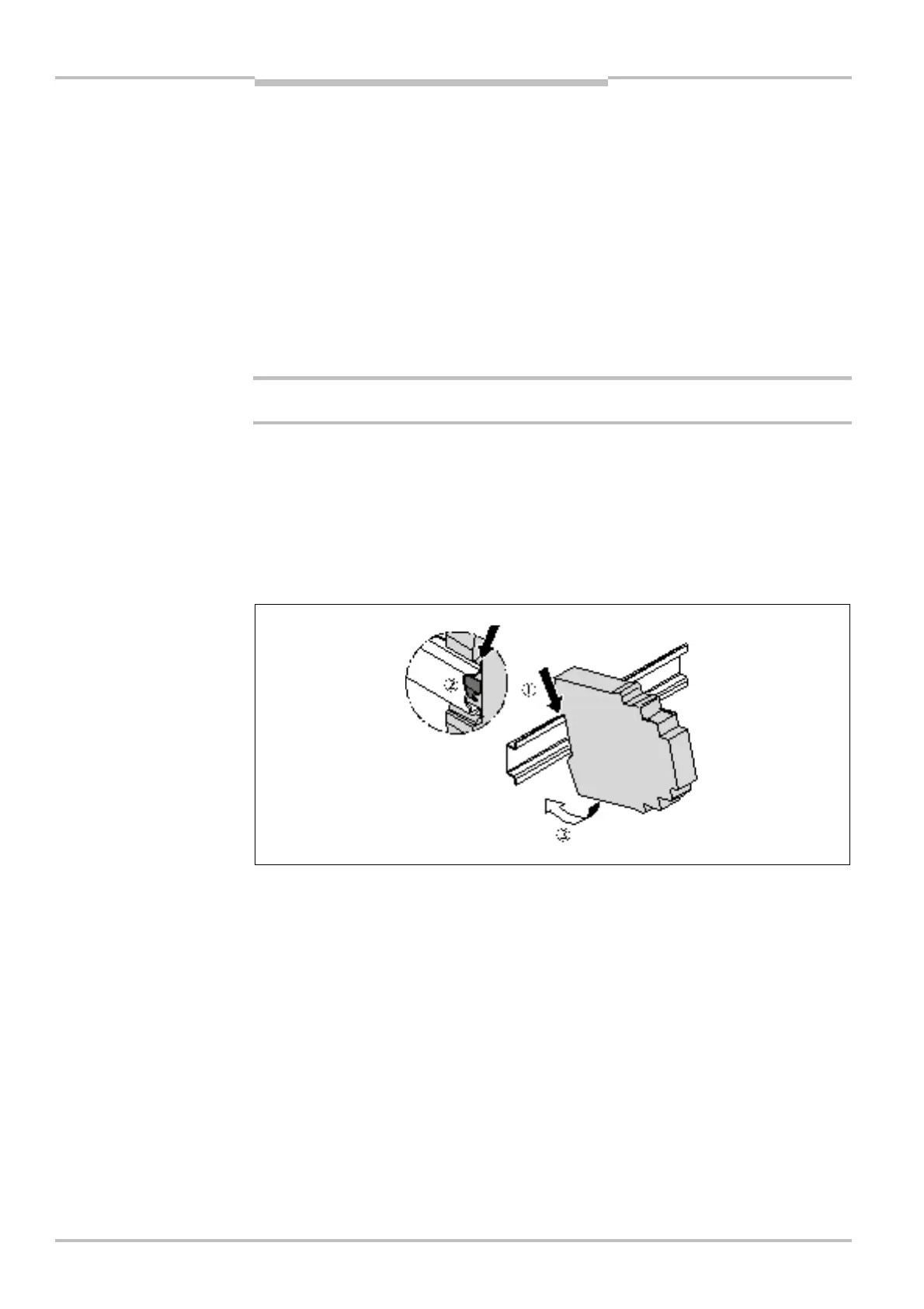
= Hang the device onto the DIN mounting rail (0).
= Ensure that the earthing spring contact is positioned correctly (1). The earthing spring
contact of the module must contact the DIN mounting rail making good electrical
contact.
= Latch the module onto the DIN mounting rail by pressing it lightly in the direction of the
arrow (2).
WARNING
into the DIN mounting rail

 Loading...


