Operating instructions Chapter 3
Flexi Classic
8011509/YPP0/2015-10-26 © SICK AG • Industrial Safety Systems • Germany • All rights reserved 19
Subject to change without notice
Product description
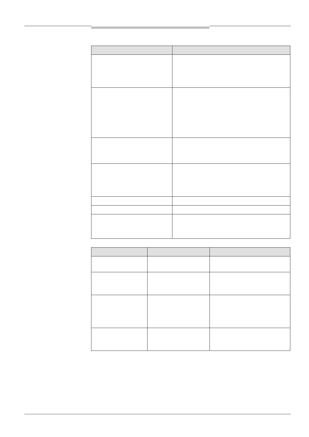
3.2.7 Module overview, adjustments and facilities for connecting sensors
Module Description
UE410-MU
• Main unit of the Flexi Classic modular safety
controller
• 4 safe inputs and 4 safe outputs
• Storage of the system configuration
UE410-GU
• Central function block of the Flexi Classic
modular safety controller
• Global emergency stop can be realized
• 4 safe inputs
• 1 safe output
• Storage of the system configuration
UE410-XU • Input/output extension/subsystem
• 4 safe inputs and 4 safe outputs
• Identical functionality as UE410-MU
UE410-8DI • Input extension
• 8 safe inputs
• Information coupling to the upstream UE410-
MU, UE410-GU or UE410-XU module
UE410-2RO 2 contacts (N/O), 1 signal contact (N/C)
UE410-4RO 4 contacts (N/O), 2 signal contacts (N/C)
Flexi Classic gateways
e.g. UE410-PRO, UE410-DEV,
UE410-CAN
Status and diagnostics (information that is not
safety relevant) of a Flexi Classic on a fieldbus
(see Flexi Classic Gateways operating instructions)
Setting possibility Can be set at the module Comment
ENTER button UE410-MU/UE410-GU
Saving of all Flexi Classic system
programs, settings and wiring
Program 1-9
UE410-MU/UE410-
GU/UE410-XU
Selection of the safety sensors
and of the logic elements to be
connected
Off delay
0-5 s, 0-50 s or
0-300 s
UE410-MU/UE410-XU
Delays 1 or 2 outputs on the
module
3 different variants available
(Not on UE410-xxxT0)
Switch position 0-9 UE410-8DI
Selection of the logic elements
and of the safety sensors to be
connected
possibilities

 Loading...


